RoadRunner HD™ | High Definition Mobile Recorder
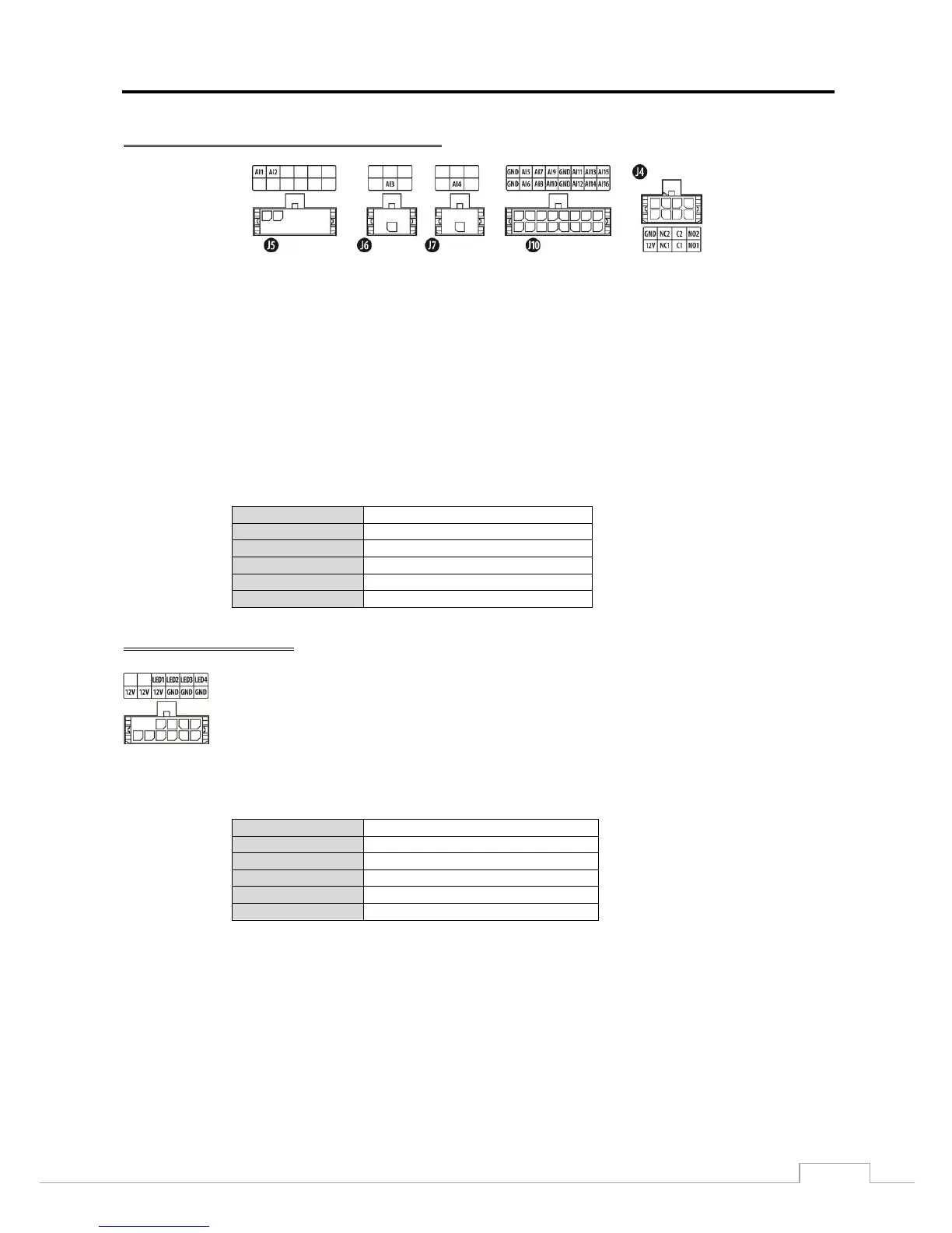
Alarm Connection – J5, J6, J7, J10 and J4
AI 1 to 16 (Alarm-In): Use external devices to signal events to the Recorder. Mechanical or electrical switches can
be wired to the AI (Alarm-In) and GND (Ground) connectors. The voltage range is from 0V to 50V. When the electrical
switch is wired, the threshold voltage for NC (Normally Closed) is below 2.5V and for NO (Normally Open) is above
2.6V, and it should be stable at least 0.5 seconds to be detected.
GND (Ground): Connect the ground side of the Alarm input and/or alarm output to the GND connector.
All the connectors marked GND are common.
NC 1 to 2 /NO 1 to 2 (Relay Alarm Outputs): The Recorder can activate external devices such as buzzers or lights.
Connect the device to the C (Common) and NC (Normally Closed) or C and NO (Normally Open) connectors. NC/NO
is a relay output which sinks 0.5A@125VAC and 1A@30VDC. See Chapter 3 ─ Configuration for configuring alarm
output.
Relay Alarm Outputs 1 to 2
(Normally Closed)
Relay Alarm Outputs 1 to 2
(Normally Open)
The Recorder can activate external LED devices. Heartbeat (LED 1), recording status (LED 2),
alarm status (LED 3) and test (LED 4) outputs are provided (50mA@12VDC).
LED 1: The heartbeat LED blinks at a constant rate as long as the Recorder is operating
and stops blinking if the Recorder stops operating.
LED 2: The recording status LED blinks when the Recorder is recording on the hard
disk drive.
LED 3: The alarm status LED is lit when a configured alarm output is activated.