Do you have a question about the Apollo RP4A and is the answer not in the manual?
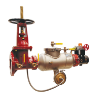
Explains the components and function of the RP device, including check valves and relief valve.
Covers placement, flushing, and orientation for installing the RP device.
Details drainage, freezing, and strainer considerations for RP installation.
Lists symptoms, causes, and corrective actions for common operational problems.
Procedure for removing check modules from 2-1/2" to 6" valves.
Cleaning or replacing check valve discs on 2-1/2" to 6" models.
Details servicing the relief valve on 2-1/2" to 6" models.
Procedure for removing check modules from 8" to 12" valves.
Specific relief valve maintenance procedures for 8" models.
Specific relief valve maintenance procedures for 10" and 12" models.
Verifies the pressure differential relief valve's function.
Checks if check valve No. 2 holds against back pressure.
Measures static pressure drop across check valve No. 1.
Procedure for testing the bypass single check on RPDA Type 2.
Explains RPDA Type 1 and Type 2 assemblies and their operation.
Covers placement and general installation of RPDA units.
Provides additional advice for RPDA installation, including drainage and freezing.
Steps for taking apart and putting together the bypass check valve module.
Steps for servicing the relief valve in the bypass RP (Type 1).
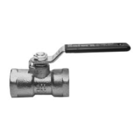
Lists part numbers for various 2-1/2" shut-off valve configurations.
Lists part numbers for various 3" shut-off valve configurations.
Lists part numbers for various 4" shut-off valve configurations.
Lists part numbers for various 6" shut-off valve configurations.
Lists part numbers for various 8" shut-off valve configurations.
Lists part numbers for various 10" shut-off valve configurations.
Lists part numbers for various 12" shut-off valve configurations.
| Category | Control Unit |
|---|---|
| Model | RP4A |
| Processor | ARM Cortex-A53 |
| Connectivity | Wi-Fi 802.11 a/b/g/n |
| Ports | USB-C, 3.5mm Headphone Jack |