600840-000031 Stratus ES/ESG Installation Instructions
Rev. 2.2
Last Revised: February 20, 2018
Page 5 of 45
List of Figures
Figure 1: Locking mechanism location ......................................................................................19
Figure 2: Pin-out .......................................................................................................................21
Figure 3: Ambient light sensor location .....................................................................................32
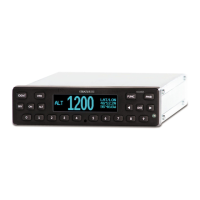
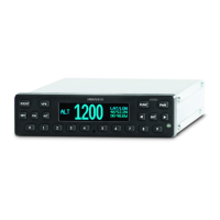
Figure 4: Stratus ES/ESG front panel ........................................................................................36
Figure 5: Pressure Altitude screen ............................................................................................37
Figure 6: GPS screen ................................................................................................................37
Figure 7: Flight ID screen ..........................................................................................................37
Figure 8: Brightness screen ......................................................................................................37
Figure 9: Flight ID entry screen .................................................................................................39
List of Tables
Table 1: TSO compliance ..........................................................................................................11
Table 2: TSO deviations ............................................................................................................11
Table 3: Criticality level .............................................................................................................12
Table 4: Embedded hardware and software ..............................................................................13
Table 5: Equipment dimensions ................................................................................................13
Table 6: Equipment weight ........................................................................................................13
Table 7: Electrical specifications ...............................................................................................14
Table 8: Power requirements ....................................................................................................14
Table 9: Required tools .............................................................................................................14
Table 10: Required hardware (supplied parts) ..........................................................................15
Table 11: Required hardware (additional parts).........................................................................15
Table 12: Compatible GPS antenna ..........................................................................................16
Table 13: Compatible transponder antenna ..............................................................................17
Table 14: Pin assignments ........................................................................................................21
Table 15: Power pin assignments .............................................................................................22
Table 16: Parallel altitude encoder pin assignments .................................................................22
Table 17: Serial altitude encoder pin assignments ....................................................................23
Table 18: Suppression pin assignments ....................................................................................23
Table 19: Aircraft lighting bus pin assignments .........................................................................23
Table 20: External IDENT pin assignment .................................................................................23
Table 21: External standby pin assignment ...............................................................................24
Table 22: Squat switch pin assignment .....................................................................................24
Table 23: Keys used during configuration .................................................................................25
Table 24: BIT diagnostic codes .................................................................................................30
Table 25: Mode selection keys ..................................................................................................36
Table 26: Event indicators .........................................................................................................36
Table 27: DO-160G tests performed .........................................................................................45