COPYRIGHT © APPLANIX CORPORATION, 2017
ALL RIGHTS RESERVED. NO PART OF THIS PUBLICATION MAY BE REPRODUCED, STORED IN A RETRIEVAL SYSTEM OR TRANSMITTED IN ANY FORM
OR BY ANY MEANS WITHOUT THE PRIOR WRITTEN CONSENT OF APPLANIX CORPORATION.
4
5. Hardware Interface
The hardware interface consists of three connectors:
One I/O connector
Two GNSS antenna connectors
All pins on the 44-pin I/O connector are ESD protected. They are tested according to IEC
61000-4-2 level 4, 8kV contact, 15kV air discharge.
None of the lines on I/O connector isolated. All voltage levels are referenced with respect
to the signal ground.
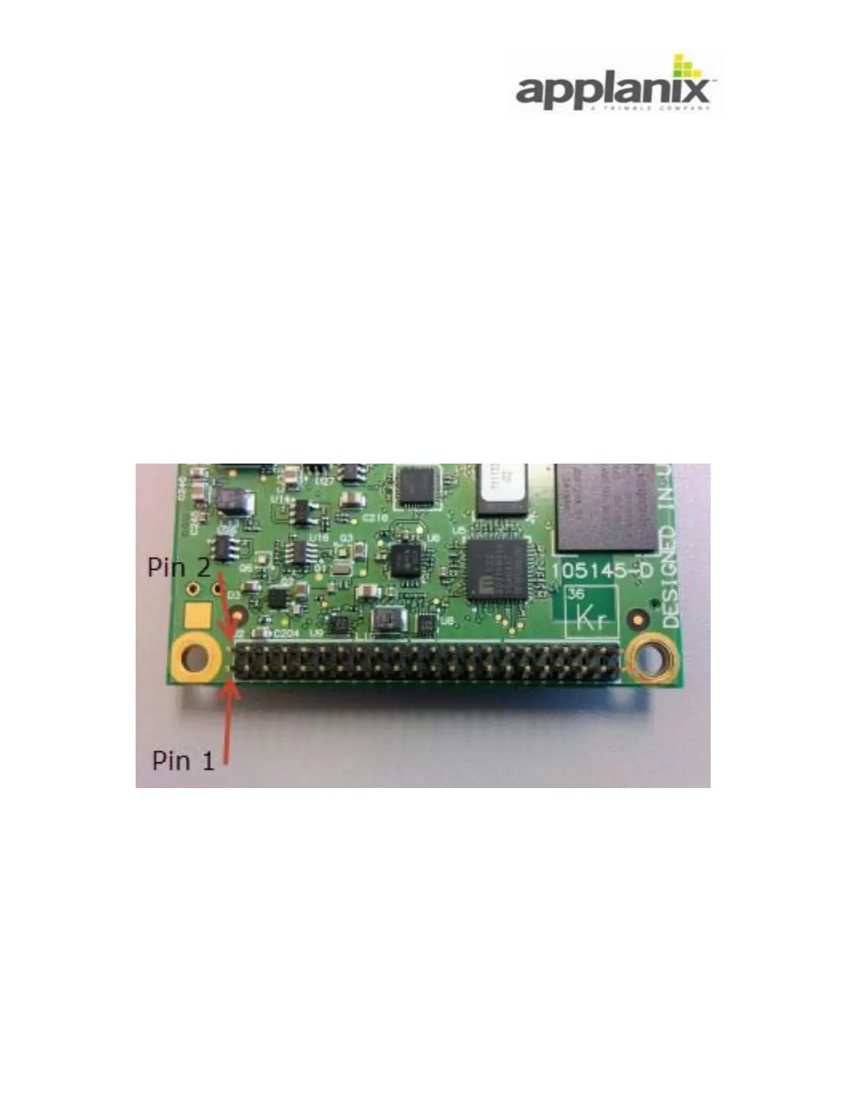
5.1. I/O Connector Pin-out
The I/O connector is a PCB mounted 44 pin header, male type (Samtec TMM-122-03-S-
D-MW). The pin enumeration is labelled on Figure 3.
Figure 3: I/O Connector Pin Enumeration
The I/O connector pin-out functionality is specified in Table 1.
Note: All signal types marked as TTL refer to standard 3.3V TTL.