– 31 –
SECTION IX - MAXITROL VALVE ADJUSTMENTS
AND PRELIMINARY CIRCUIT ANALYSIS
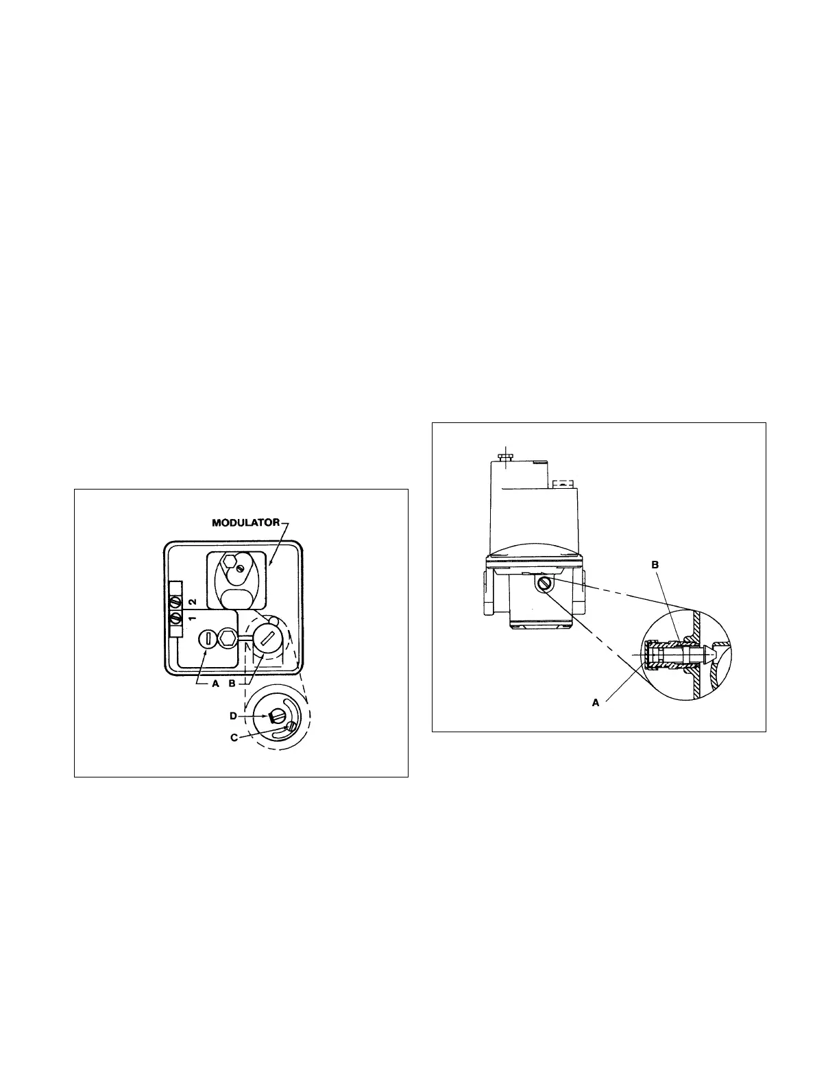
MR212 Valve
High Fire Manifold Adjustments
1. Disconnect wires from amplifier terminal #4 (Series
14), or #2 and #4 (Series 44). This causes the
valve to call for continuous high fire.
2. Remove seal cap (A) and turn regulator pressure
adjusting screw to obtain desired manifold pres-
sure. (Clockwise rotation increases pressure.)
3. Reconnect the wires to amplifier terminal #4
(Series 14), or #2 and #4 (Series 44).
NOTE: If low bypass is on maximum, the desired
high fire outlet pressure may not be achieved.
Low Fire or Bypass Adjustments
1. Disconnect wire from amplifier terminal #8. This
causes valve to call for continuous low fire.
2. Remove cap (B) and loosen lock screw (C). Turn
(D) to desired low fire adjustment. (Clockwise
rotation reduces minimum flow rate.)
3. Tighten screw (C), replace cap (B) and reconnect
wire to amplifier to terminal #8.
M411, 511, 611 Valve
High Fire Manifold Adjustments
1. Disconnect wires from amplifier terminal #4 (Series
14), or #2 and #4 (Series 44). This causes the
valve to call for continuous high fire.
2. Adjust the pressure regulator to obtain the desired
manifold pressure (7" w.c. maximum).
3. Reconnect the wires to amplifier terminal #4
(Series 14) or #2 and #4 (Series 44).
Low Fire or Bypass Adjustments
1. Disconnect wire from amplifier terminal #8. This
causes the valve to call for continuous low fire.
2. Remove cap (A) and turn adjusting screw (B) to
desired low fire adjustment. (Clockwise rotation
reduces minimum flow rate.)
3. Replace cap (A) and reconnect wire to amplifier
terminal #8.