– 33 –
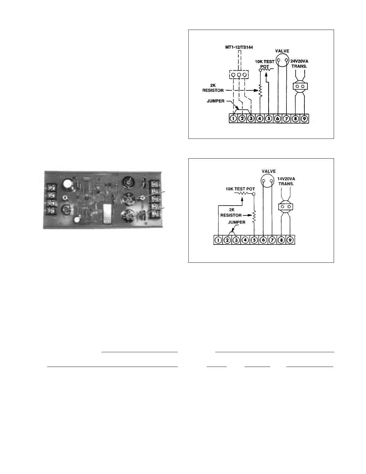
Figure 1
Figure 2
Dealer/Contractor Name:
City:
Address:
State: Zip: Ph:
MAX
MIN
SECTION X-REPLACEMENT PARTS
Replacement parts may be ordered from the factory.
All warranty parts will be shipped freight allowed from
factory for normal ground service. Warranty parts must be
returned prepaid within 30 days. Credit will be issued if
part is complete, defective and returned on time.
When parts are ordered, MODEL NUMBER, SERIAL
NUMBER, FACTORY ORDER (F.O.) and PART
NUMBERS are required. Belts, filters, and fuses are
not covered under warranty.
Section 4
1. With proper voltages observed thus far and modu-
lator responding correctly, wire the system (see
Figure 1), except have TS144 connected in place
of jumper. Set A1044 MIN temperature selector at
least 10°F above outdoor temperature. Set A1044
MAX temperature selector at mid-range. Heater is
now under control by TS144 Discharge Air Monitor.
2. Turn Test-Potentiometer to maximum resistance.
Delivered air temperature should be per A1044
MAX temperature setting. Turn Test-Potentiometer
to minimum resistance. Delivered air temperature
should be per A1044 MIN temperature setting.
If proper delivered air temperatures are observed,
the problem is identified with the space temperature
sensing and/or temperature selecting components
and circuits. See Troubleshooting Guide.
If proper delivered air temperatures are not
observed, check calibration. See Troubleshooting
Guide.
Section 5
1. After test, remove all test equipment and reconnect
all components.