Applied Systems Engineering, Inc.
Page 2
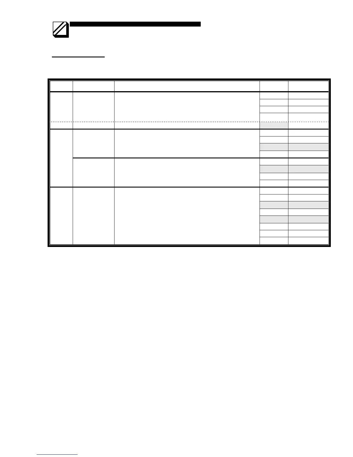
Switch Settings
• Settings Apply to Both Rack Mount (5008) and Box Mount (5006) Modem
•
Bold Italics indicates factory settings
Switch Usage Notes Position Value if ON
1 -1 dB
2 -2 dB
3 -4 dB
SW1 Transmit gain
• 0 to –31 dB
• Add values for all switches in the ON position and add
0 to sum of switch values if JP7 is installed and add
–16 if JP7 is removed. 4 -8 dB
JP7 JP7 (See Jumper Settings)
installed
1 2 msec
2 4 msec
3 8 msec
CD On Delay
• Delay in setting RS-232 “CD” signal after carrier is
detected, 2 to 30 milliseconds
• Add values for all switches in the ON position
• At least one switch must be ON
4 16 msec
5 1 msec
6 2 msec
7 4 msec
SW3
900Hz soft-
carrier turn-off
• Soft-carrier turnoff duration, 1 to 15 milliseconds
• Add values for all switches in the ON position.
• At least one switch must be ON
8 8 msec
1 0 msec
2 2 msec
3 4 msec
4 8 msec
5 16 msec
6 32 msec
7 64 msec
SW4 RTS/CTS
• Delay between requesting RTS and granting CTS, 0 to
254 milliseconds or constant
• If switch 1 is OFF, add values for all switches (2 to 8)
in ON position.
• If all switches are OFF, CTS is constantly enabled
8 128 msec