Applied Systems Engineering, Inc.
Page 4
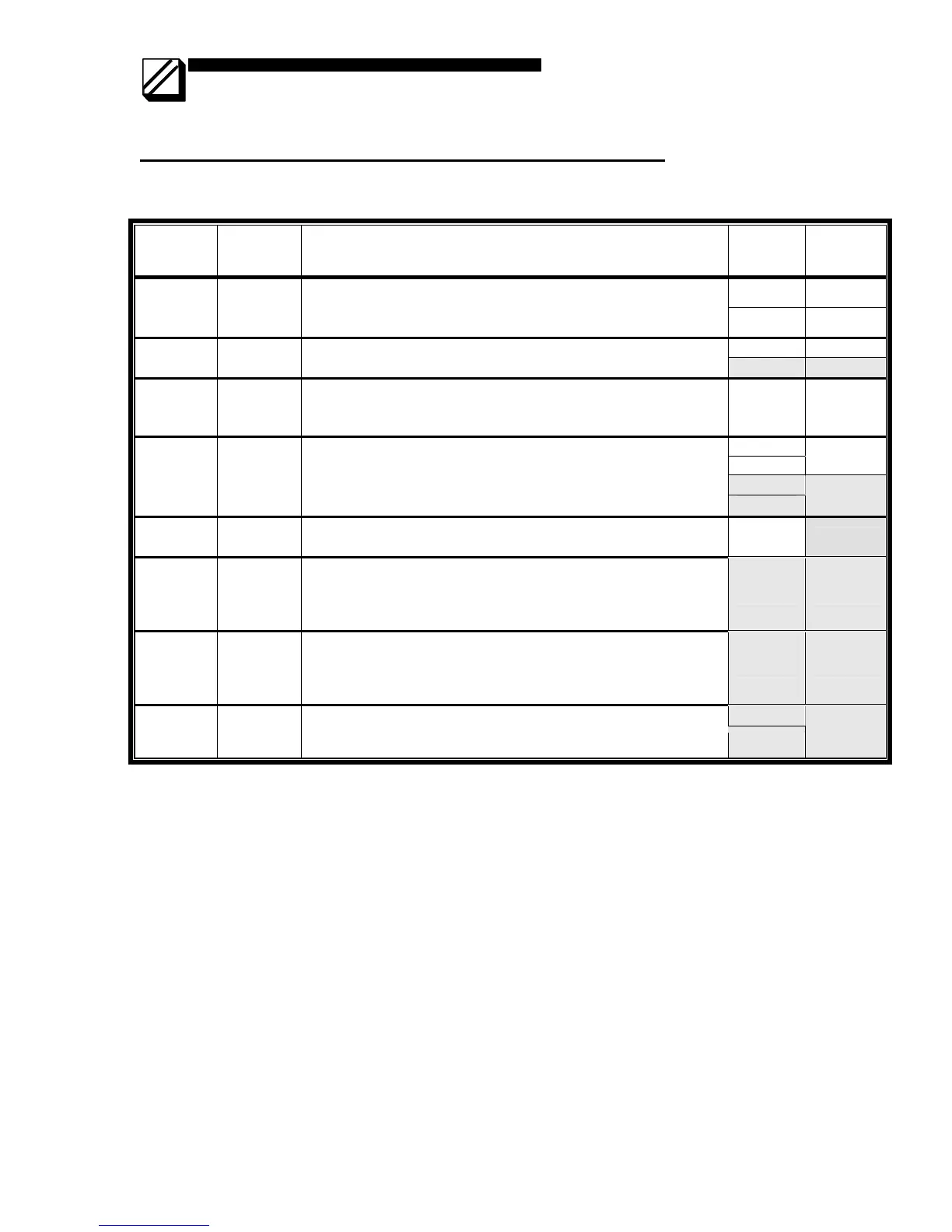
Jumper Settings for Rack Mount (5008) Modem (Rev A)
• Bold Italics indicates factory settings
Jumper Usage Notes Jumper Meaning
1-2 DSR
JP1 DTR/DSR
• Uses DTR as “clear-to-send” signal, instead of CTS
• Uses DSR as “request-to-send” signal instead of RTS
• Normal mode (RTS/CTS) has no jumpers installed
3-4 DTR
1-2 -45 dB JP2 Receiver
gain
• Sets receiver gain to –35 or –45 dB
• Exactly one jumper must be installed
3-4 -35 dB
JP3 Receiver
squelch
• For half duplex mode, adds 156 millisecond delay between
end of transmitted message and enabling receiver
• Receiver constantly enabled if not installed
1-2 156 msec
1-2
3-4
2-wire
5-6
JP4 2W/4W
• Selects 2-wire (half duplex) or 4-wire (full-duplex) operation
• Exactly 2 jumpers must be installed
7-8
4-wire
JP5 Carrier
• Selects switched or constant carrier
• Remove jumper for switched carrier
1-2
Removed
JP6 900Hz
soft
carrier
turn-off
• Installed if 900Hz-carrier turn-off is not required.
• Removed if 900Hz-carrier turn-off is required.
• Note: Must be installed for V.23 CCITT operation
1-2 Installed
JP7 Transmit
level
range
selection
• If installed, SW1 settings interpreted as 0 to –15 dB
• If removed, SW1 settings interpreted as –16 to –32 dB
1-2 Installed
3-5
JP9 Reserved
• These jumpers are factory installed and must not be altered
after shipment.
4-6
Installed