EVM4X, WMVM: Installation Instructions
Manufacturer reserves the right to change, at any time, specifications and designs without notice and without obligations.
6
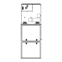
Horizontal Right Installation
1. Use field fabricated attachment plates to secure coil to furnace
(Fig. 9).
2. Use self-tapping screws to mount attachment plates to coil casing.
Install screws no more than 1" from the outer edge to avoid
contacting or interfering with internal components.
3. Connect furnace snugly against coil casing.
A221202
Fig. 9 – Horizontal Right Attachment Plates
4. Use self-tapping screws to attach furnace (Fig. 10).
A221203
Fig. 10 – Horizontal Right Installation
5. Seal joint between coil casing and furnace to create an air tight seal
using locally approved materials.
6. If coil is wider than furnace, use 18-in minimum transition and self
tapping screws to attach furnace (Fig. 8).
Horizontal Right with Pan Extension (6124 Size Only)
The pan extension is shipped with the unit. There should not be any gaps
between the plastic condensate pan and the pan extension. All
condensate should flow from the pan extension to the plastic condensate
pan and not leak into the coil cabinet or duct.
Install the pan extension onto the right end of the horizontal-condensate
pan. The pan extension is slotted to fit onto the condensate pan edge and
will extend into the supply plenum (Fig. 11).
A221204
Fig. 11 – Horizontal-Right Pan Extension (6124 size only)
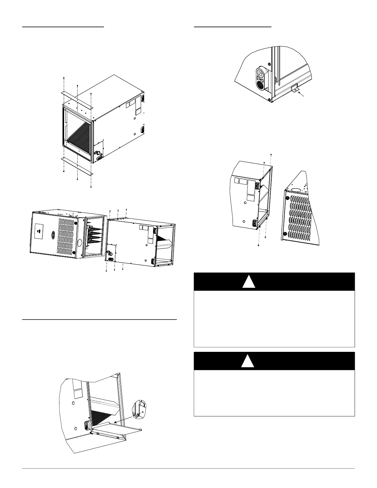
Horizontal Left Installation
1. Unbend the 4 tabs at the right side of the casing (Fig. 12).
2. Connect furnace snugly against coil casing.
A221205
Fig. 12 – Horizontal Left Installation
3. Use self-tapping screws to attach furnace (Fig. 13).
4. Seal joint between coil casing and furnace to create air tight seal
using locally approved materials.
5. If coil is wider than furnace, use 18-in. minimum transition and self
tapping screws to attach furnace (Fig. 8).
A221206
Fig. 13 – Horizontal Left Installation
Refrigerant Line Connections
NOTE: Factory nitrogen charge may escape past rubber plugs during
storage. This does not indicate leaking coil nor warrant return of the coil.
Size and install refrigerant lines according to information provided with
outdoor unit. Coil connection tube sizes are shown in Table 1. Route
refrigerant lines to the coil in a manner that will not obstruct service
access to the unit or removal of the filter.
CAUTION
!
WATER MANAGEMENT HAZARD
Failure to follow this caution could cause product and/or property
damage.
The furnace coil door must be properly installed when the coil is in
operation. To ensure proper condensate water management, the drain
pan must not touch the coil. When properly installed the furnace coil
door will correctly align the condensate pan with the coil.
WARNING
!
PERSONAL INJURY HAZARD
Failure to follow this warning could result in personal injury.
Wear eye protection. Coil is factory charged with 7–10 psi nitrogen.
The coil is under pressure and TXV screen is in place behind liquid line
plug. DO NOT remove liquid line plug first, always remove the suction
line plug first to depressurize the coil.
 Loading...