HOW IT WORKS
When the Automatic Humidifier Control calls for humidity:
• The solenoid valve opens and water flows into the water panel evaporator. Water enters the right float chamber.
• As water enters the float chamber, the float inside begins to rise. This breaks the electrical connection with the
water level sensor and shuts the unit off by disconnecting power to the solenoid valve.
• Water in the float chamber wicks up the panel and is evaporated as the furnace moves air through it.
• As water wicks up, the float drops down and makes contact with the water level sensor assembly. This restores
the electrical connection and opens the solenoid valve. The entire process repeats itself until the furnace blower
shuts off or the humidistat is satisfied.
PRODUCT SPECIFICATIONS
Evaporative Capacity: .7 g.p.h. / 17 g.p.d.
Area It Will Handle:
• Loose House (2 air changes per hour) - 1000 sq.ft.
• Average House (1 air change per hour) - 2000 sq.ft.
• Tight House (1/2 air change per hour) - 4000 sq.ft.
Unit Size (Inches): 14" W x 15
1/8
" H x 10
3/8
" D
Bypass Connection: 6" round
Plenum Opening: 9" W x 12" H
Electrical data: 24 V - 60 Hz - 0.5 amp
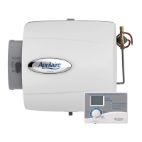
Models: 400 - Includes premium automatic
digital control
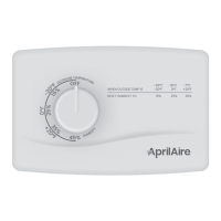
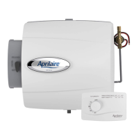
400M - Includes manual control
THE SERIES 400 INCORPORATES SEVERAL SAFETY FEATURES
The left float chamber operates as a safety back-up to the right float. In the unlikely event the right float failed and
water continued to fill the chamber, the water would spill into the left float chamber and shut off power to the solenoid
valve. This chamber is isolated from the wicking action of the water panel and the air coming through the humidifier.
During the heating season, water in the isolated back-up chamber will evaporate over approximately two days. If the left
chamber dries out, the safety float would engage the solenoid valve, but the system would again shut down. This design
eliminates overflows.
If both floats were to fail, water would flow out of the left-hand float chamber and into the center of the scale control
insert, which would direct the water to the safety overflow connection at the bottom of the humidifier.
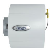
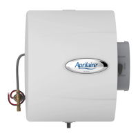
SERIES 400 AUTOMATIC HUMIDIFIER
P.O. BOX 1467 • MADISON, WI 53701-1467 • Phone 608/257-8801 • FAX 608/257-4357 • www.aprilairecontractor.com
Form No. 215 07.13 © 2013 Research Products Corporation
 Loading...