Do you have a question about the Aprilaire 600M and is the answer not in the manual?
Covers critical electrical, scalding, and property damage risks. Essential for safe installation.
Details humidifier dimensions, bypass duct opening, plenum opening, water feed rate, and electrical data.
Provides wiring diagrams for Model 600M (Manual Control) and Model 600A (Automatic Control).
Illustrates common installation configurations for upflow and horizontal systems.
Step-by-step guide from preparing the unit to final operational checks.
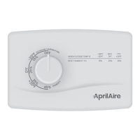
Details on mounting and wiring the manual control unit for the humidifier.
Instructions for mounting and wiring the automatic digital control unit.
Guidance on connecting water supply, drain lines, and verifying proper operation.
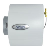
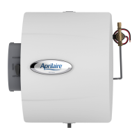
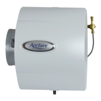
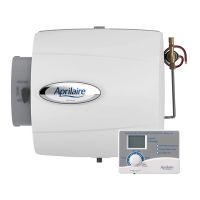
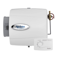
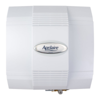
The Aprilaire Large Bypass Humidifier, available in Model 600M (Manual Control) and Model 600A (Automatic Digital Control), is designed to integrate with forced air handling systems to introduce humidity into a home's environment. This device is intended for installation by qualified heating and air conditioning contractors, ensuring proper setup and adherence to safety standards.
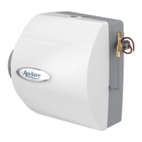
The primary function of the Aprilaire humidifier is to add moisture to the air circulating through a home's heating and cooling system. This process helps maintain optimal indoor humidity levels, which can alleviate issues associated with dry air, such as dry skin, static electricity, and damage to wood furnishings. The humidifier operates by drawing water from a supply line, which then flows over a Water Panel® Evaporator. As air from the furnace's supply or return plenum passes through the humidifier, it absorbs moisture from the wetted Water Panel®, and this humidified air is then distributed throughout the home. Excess water, along with any mineral deposits, is directed to a drain.
The Model 600M features a Manual Humidifier Control, allowing the homeowner to set the desired humidity level manually. This control can be mounted in the return duct or on a wall in the living space. The humidifier will activate when the furnace is operating and the indoor relative humidity (RH) falls below the set point on the control.
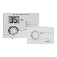
The Model 600A, on the other hand, incorporates an Automatic Digital Humidifier Control. This advanced control system automatically adjusts humidity output based on outdoor temperature and indoor conditions, providing a more consistent and comfortable humidity level without constant manual adjustments. It typically includes an outdoor temperature sensor to prevent condensation on windows during colder weather. The digital control requires a continuous 24V power source and is usually mounted on the return duct, with its RH sensor extending into the duct opening to accurately measure humidity.
Both models utilize a bypass design, meaning a portion of the air from the supply plenum is diverted through the humidifier and then returned to the return plenum, or vice versa, depending on the installation configuration. An integral bypass damper allows the user to switch between "WINTER" (open) for humidification during the heating season and "SUMMER" (closed) when humidification is not needed, such as during the cooling season.
The Aprilaire humidifier is designed for flexible installation, capable of being mounted on either the supply or return plenum of a forced air system. Its design allows for easy reversibility, accommodating both right-hand and left-hand bypass duct connections. This adaptability ensures that the humidifier can be integrated into various existing HVAC setups.
The humidifier can operate with cold, hot, softened, or unsoftened water. However, using hot water (up to 140°F max) is recommended, especially with heat pump systems, as the heated water supplements the reduced supply air temperature, providing added heat for more efficient evaporation and greater evaporative capacity. A saddle valve is provided for tapping into the water supply line, and it is crucial to ensure this valve is either fully opened or closed, not used to regulate flow.
The control unit, whether manual or automatic, plays a key role in managing the humidifier's operation. For the manual control, the homeowner simply turns a knob to adjust the desired humidity. For the automatic digital control, the system largely manages itself, though users can typically override settings or switch to a manual mode if desired. The digital display provides feedback on current humidity levels and settings.
Safety is a paramount consideration. Installers are warned about electrical shock hazards, sharp edges during installation, and the risk of scalding from hot water. The manual also cautions against installing the humidifier in areas prone to freezing temperatures, on the furnace jacket, or where airflow might be restricted by cooling coils. It also advises against setting humidity levels too high, especially in unheated spaces, to prevent condensation damage and potential mold growth. The humidifier should not be installed on systems with excessive pressure differential between supply and return plenums.
Maintenance of the Aprilaire humidifier primarily involves the periodic replacement of the Water Panel® Evaporator and ensuring the drain line remains clear. The design facilitates easy access for these tasks. To access the Water Panel® Evaporator, the front cover can be removed by pressing the top and bottom tabs. The feed tube is then pulled out of the distribution tray, allowing the Water Panel® Evaporator assembly to be removed.
The Water Panel® Evaporator is a critical component that collects mineral deposits from the water as it evaporates. Regular replacement, typically once per heating season, ensures optimal performance and prevents the buildup of minerals that could impede humidification efficiency. The scale control insert, which is part of the Water Panel® Evaporator assembly, helps manage mineral deposits.
The drain line, which carries away excess water and flushed minerals, needs to be checked periodically to ensure it has a constant downward slope and is not kinked, preventing blockages and potential water damage. The manual emphasizes not to over-tighten the hose clamp onto the drain spud or use solvent adhesive on the drain spud, as this could damage components or create leaks.
The humidifier's robust construction and straightforward design aim to minimize complex maintenance procedures, allowing for easy upkeep by the homeowner or a service technician. The importance of proper installation by a qualified contractor is stressed, as incorrect installation can void the warranty and lead to operational issues. The owner's manual, containing detailed instructions for operation and warranty information, is intended to be given to the homeowner to ensure they are well-informed about the device's care and use.
| Type | Bypass |
|---|---|
| Coverage Area | Up to 4, 000 sq. ft. |
| Capacity | 17 gallons per day |
| Control Type | Manual |
| Weight | 12 lbs |
| Voltage | 24 V |
| Current Draw | 0.5 A |
| Water Panel Life | 1 season |
| Drain Required | No |
| Installation | Ducted to HVAC system |
| Water Usage | Up to 17 gallons per day |
| Humidifier Output | 0.7 gallons per hour |