18
use and maintenance Classic 125
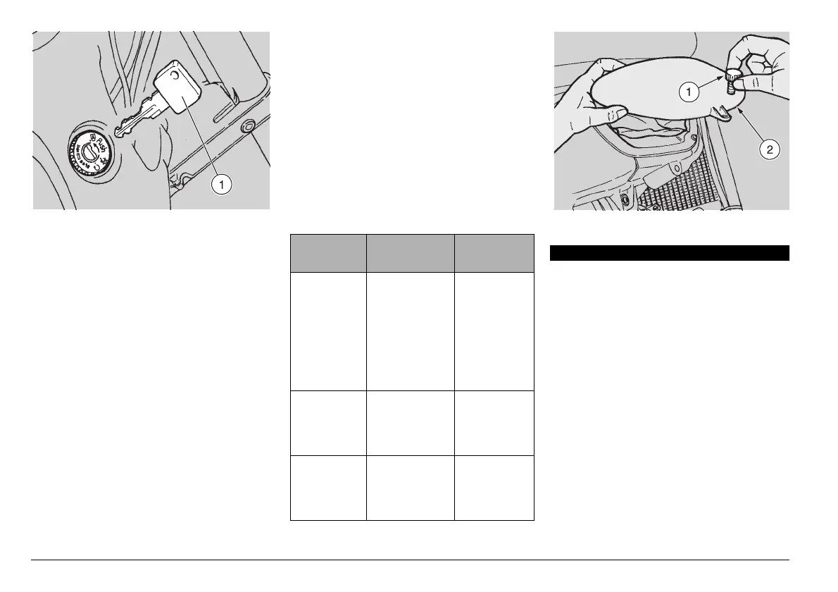
IGNITION SWITCH (Fig. 7)
The ignition switch is positioned on the
right side of the vehicle, between the fuel
tank and the steering tube (Fig. 7).
The key (1) operates the ignition
switch/steering lock, the saddle
lock and the fuel tank lock.
Two keys are supplied together with the
vehicle (one spare key).
STEERING LOCK (Fig. 7)
Never turn the key to position
"
s" in running conditions, in or-
der to avoid losing control of the
vehicle.
OPERATION
To lock the steering:
◆
Turn the handlebar completely leftwards.
◆
Turn the key to position "m" and press it.
◆
Release the key and turn it to position
"
s".
◆
Extract the key.
AUXILIARY EQUIPMENT
TOOL KIT (Fig. 8)
To reach the tool kit (right side of the vehi-
cle), unscrew and remove the knob (1) and
remove the cover (2).
The tool kit includes:
n. 1 25 mm spark plug spanner
n. 1 3 mm hexagon spanner
n. 1 cross-/cut-headed screwdriver + 4 mm
hexagon spanner
n. 1 3 mm hexagon spanner
n. 1 screwdriver handle
n. 1 tool case
Fig. 7
c
Position Function
Key
removal
s
Steering
lock
The steering is
locked.
It is neither
possible to
start the
engine, nor to
switch on the
lights.
It is possible
to remove
the key.
m
Neither the
engine, nor the
lights can be
switched on.
It is possible
to remove
the key.
n
The engine
and the lights
can be
switched on.
It is not pos-
sible to
remove the
key.
a
Fig. 8
 Loading...