EasyManua.ls Logo

APRILIA SHIVER 750 ABS 2010 User Manual

APRILIA SHIVER 750 ABS 2010
185 pages
To Next Page IconTo Next Page
Page #1 background imageLoading...
Page #1 background image
APRILIA WOULD LIKE TO THANK YOU
for choosing one of its products. We have drawn up this booklet to provide a comprehensive overview of your vehicle's quality features. Please read it
carefully before riding the vehicle for the first time. It contains information, tips and precautions for using your vehicle. It also describes features, details
and devices to assure you that you have made the right choice. We believe that if you follow our suggestions, you will soon get to know your new vehicle
well and will use it for a long time at full satisfaction. This booklet is an integral part of the vehicle, and should the vehicle be sold, it must be transferred
to the new owner.
APRILIA WIL U BEDANKEN
omdat u één van haar producten heeft gekozen. Wij hebben deze handleiding opgesteld opdat u de kwaliteiten ervan ten volle kan waarderen. Wij
raden aan om deze handleiding geheel door te lezen, voordat u met het voertuig gaat rijden. Het bevat informatie, raadgevingen en waarschuwingen
in verband met het gebruik van uw voertuig; daarnaast zal u eigenschappen, bijzonderheden en handigheidjes ontdekken die u ervan zullen overtuigen
dat u een juiste keuze heeft gemaakt. Wij zijn er zeker van dat indien u hier rekening mee zal houden, u makkelijk zal wennen aan uw nieuw voertuig,
waar u lang naar volle tevredenheid gebruik van zal kunnen maken. Deze uitgave is een integrerend deel van het voertuig, en bij verkoop van dit laatste
moet het worden overhandigd aan de nieuwe eigenaar.
SHIVER 750 - SHIVER 750 ABS
Ed. 04 2010

Table of Contents

Question and Answer IconNeed help?

Do you have a question about the APRILIA SHIVER 750 ABS 2010 and is the answer not in the manual?

APRILIA SHIVER 750 ABS 2010 Specifications

General IconGeneral
Engine TypeV-twin, 4-stroke
Displacement749.9 cc
Compression ratio11.0:1
Fuel systemElectronic Fuel Injection
Transmission6-speed
Final driveChain
ABSYes
Front Tire120/70 ZR17
Rear Tire180/55 ZR17
Dry Weight189 kg
Bore x stroke92 x 56.4 mm
IgnitionElectronic
Cooling systemLiquid-cooled
Maximum Power95 hp (70 kW) @ 9000 rpm
Maximum Torque81 Nm @ 7, 000 rpm
Front BrakesDual 320 mm discs
Seat Height810 mm
Fuel Capacity15 liters
FrameModular tubular steel frame
Rear BrakesSingle 245 mm disc, single-piston caliper

Summary

Personal safety

Safeguarding the environment

Vehicle intactness

GENERAL RULES

Foreword

Maintenance operations may need to be performed at half the intervals shown if the vehicle is used in demanding conditions.

Carbon monoxide

Ensure engine running is done in well-ventilated areas to avoid carbon monoxide poisoning.

Fuel

Fuel is highly flammable and explosive; refuel and maintain in ventilated areas with the engine off.

Hot components

Engine and exhaust components get very hot; wear insulating gloves or wait for cooling before handling.

Coolant

Coolant contains ethylene glycol, which can be flammable and cause burns with invisible flames.

Used engine oil and gearbox oil

Wear latex gloves when servicing the vehicle; used oil can cause skin injuries with prolonged contact.

Brake and clutch fluid

Brake and clutch fluids can damage plastic/rubber surfaces; wear protective goggles.

Battery hydrogen gas and electrolyte

Battery electrolyte is toxic and corrosive; avoid skin and eye contact, protect eyes as acid can cause blindness.

Stand

Ensure the side stand is fully retracted before setting off; do not rest weight on the side stand.

Reporting of defects that affect safety

Do not remove mechanical or electrical components unless specified; some connectors may compromise vehicle operation if incorrectly installed.

Chap. 01 General rules

Chap. 02 Vehicle

Arrangement of the main components (02_02)

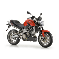
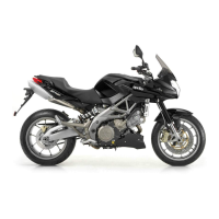
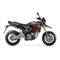
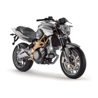
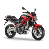
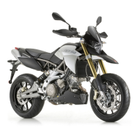
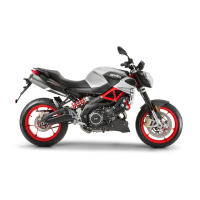
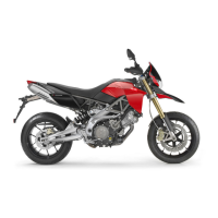
Key identifying main vehicle components, with and without ABS.

Dashboard (02_05)

Overview of dashboard layout and controls, including indicator location key.

Instrument panel (02_06)

Details the instrument panel components: RPM indicator, digital display, and warning lights.

Light unit (02_07)

Identifies the various warning and indicator lights on the vehicle's lighting system.

Digital lcd display (02_08 to 02_15)

Explains the functions and displays shown on the digital instrument panel.

Alarms (02_16 to 02_21)

SERVICE ALARM

Indicates a failure detected in the instrument panel or electronic control unit.

URGENT SERVICE ALARM

Signals serious failures with flashing lights and alternating words 'URGENT' and 'SERVICE'.

Mapping selection (02_22, 02_23, 02_24)

TOURING mapping

Mode designed for smooth tourist riding, offering balanced engine performance.

SPORT mapping

Mode for more acceleration and a sporting feel; advised for expert riders on good grip roads.

RAIN mapping

Mode for wet or low-grip conditions, reducing torque and delivering it smoothly to prevent grip loss.

Control buttons (02_25 to 02_28)

Trip journal 1 and 2

Details how to select and view data from the two available trip journals.

CHRONOMETER

Advanced functions (02_29 to 02_34)

SETTINGS

Menu for adjusting various vehicle settings like time, gear shift, backlighting, and code.

CHRONOMETER

Access and manage chronometer functions, including start, view, and delete times.

DIAGNOSIS

Menu for interfacing with vehicle systems and performing diagnostics (requires dealer access).

LANGUAGES

Option to select the desired interface language for the instrument panel.

TIME ADJUSTMENT

GEAR SHIFT THRESHOLD

BACKLIGHTING BRIGHTNESS

CODE CHANGE

CODE RESET

°C / °F

12H / 24H

CHRONOMETER

View times

Delete times

DIAGNOSIS

LANGUAGES

Ignition switch (02_35)

LOCK

Steering is locked; engine and lights cannot be activated; key can be extracted.

OFF

Engine and lights are off; key can be extracted.

ON

Engine can be started; key cannot be extracted.

Locking the steering wheel

Switch direction indicators (02_37)

Start-up button (02_39)

Engine stop switch (02_40)

Immobilizer system operation (02_41)

Fairings (02_42)

WINDSHIELD REMOVAL

Procedure to remove the windshield, involving undoing screws and detaching it from the headlamp.

Opening the saddle (02_43, 02_44, 02_45)

To lock the saddle (2)

Steps to secure and lock the saddle in place, ensuring it clicks into position.

Glove/tool kit compartment (02_46)

Identification (02_47)

CHASSIS NUMBER

Location and importance of the chassis number for parts purchasing and identification.

ENGINE NUMBER

Location of the engine number, printed on the engine crankcase.

Chap. 03 Use

Checks (03_01)

PRE-RIDE CHECKS

Essential checks before riding, including brakes, throttle, engine oil, and tires.

Refuelling (03_02)

Rear shock absorbers adjustment (03_03, 03_04, 03_05)

Front fork adjustment (03_06)

Rear brake pedal adjustment (03_08)

Clutch lever adjustment (03_09)

Running in

Starting up the engine (03_10 to 03_15)

Ride by wire

Moving off / riding (03_16 to 03_22)

To start

Procedure for starting the engine and adjusting mirrors for optimal visibility.

Stopping the engine (03_23)

When the vehicle is at a standstill

Steps for securing the vehicle after stopping, including neutral gear and brake application.

Parking

Catalytic silencer

Stand (03_24)

Suggestion to prevent theft

Basic safety rules (03_25 to 03_29)

GETTING ON THE VEHICLE

Proper procedure for mounting the motorcycle, ensuring balance and safety.

GETTING OFF THE VEHICLE

Proper procedure for dismounting the motorcycle, ensuring stability and safety.

Chap. 04 Maintenance

Engine oil level check (04_01)

Engine oil top-up (04_02)

Engine oil change (04_03)

Engine oil filter replacement (04_04, 04_05)

Tyres

CHECK TYRE INFLATION PRESSURE REGULARLY AT AMBIENT TEMPERATURE.

Importance of checking tyre pressure regularly, especially before and after long trips.

INSPECT TREAD SURFACE AND CHECK IT FOR WEAR.

Inspect tire tread for wear; worn tires compromise traction and handling.

REPLACE TYRES WHEN WORN OR IF THERE IS A PUNCTURE...

Guidelines for tire replacement based on wear or puncture size.

Spark plug dismantlement

Removing ducts (04_06, 04_07, 04_08)

Removing the air filter

Cooling fluid level (04_09, 04_10)

CHECK AND TOPPING-UP

Procedure for checking and topping up coolant, ensuring the engine has cooled down.

Checking the brake oil level (04_11, 04_12)

Braking system fluid top up

Checking clutch fluid (04_13)

Topping up clutch fluid

Use of a new battery (04_14)

Checking the electrolyte level

Charging the battery

Switch on the battery charger.

Instructions for connecting and operating the battery charger.

Long periods of inactivity

Fuses (04_15 to 04_19)

Check fuses in case of failure or irregular functioning...

Procedure for checking fuses to diagnose electrical component or engine starting failures.

To check:

AUXILIARY FUSES

MAIN FUSES - version without ABS

MAIN FUSES - version with ABS

Lamps (04_20 to 04_24)

BULB LAYOUT

Diagram and list of bulbs for the headlamp: low beam, high beam, and tail lights.

HEADLAMP BULB REPLACEMENT

LOW BEAM LIGHT BULB

HIGH BEAM BULB

TAIL LIGHT BULBS

Headlight adjustment (04_25, 04_26, 04_27)

In order to carry out vertical adjustment of the light beam:

Procedure for adjusting vertical headlight beam alignment using a screwdriver.

In order to carry out horizontal adjustment of the light beam:

Front direction indicators (04_28)

Rear optical unit

Rear turn indicators (04_29)

Number plate light (04_30, 04_31)

Rear-view mirrors (04_32, 04_33)

Front and rear disc brake (04_34, 04_35, 04_36)

To perform a quick pad wear check:

Visual inspection guide for checking front and rear brake pad wear.

Periods of inactivity (04_37)

Proceed as follows:

Steps for preparing the vehicle for storage to prevent damage from inactivity.

After storage

Cleaning the vehicle (04_38, 04_39, 04_40)

To clean off dirt and mud deposited from painted surfaces...

Instructions for cleaning painted surfaces, engine parts, and aluminum components.

TO CLEAN THE HEADLIGHTS USE A SPONGE SOAKED IN WATER AND MILD DETERGENT...

Specific instructions for cleaning headlights, emphasizing gentle rubbing and rinsing.

Transport (04_41)

Chain backlash check (04_42)

To check the clearance:

Procedure for checking chain vertical oscillation and ensuring consistent clearance.

Chain backlash adjustment

Checking wear of chain, front and rear sprockets

Also check the following parts and make sure that the chain, pinion and sprocket do not have:

Inspection of chain, pinion, and sprocket for wear, damage, or missing parts.

Chain lubrication and cleaning

Chap. 05 Technical data

DIMENSIONS

Max. length

2100 mm (82.68 in)

Max. width

800 mm (31.50 in)

Max. height (to windshield)

1135 mm (44.69 in)

Saddle height

810 mm (31.89 in)

Wheelbase

1440 mm (56.69 in)

Kerb weight

210 kg (463 lb)

ENGINE

Model

M551M

Type

90° V-twin engine with 4 valves per cylinder and 2 overhead camshafts.

Total engine capacity

749.9 cm³ (45.76 cu.in)

Bore / stroke

92 x 56.4 mm (3.62 x 2.22 cu.in)

Intake valve clearance

Exhaust valve clearance

Compression ratio

Ignition

Idle speed

Clutch

Lubrication system

Air filter

Cooling

GEARBOX

Type

6-speed mechanical gearbox with left-side foot gearshift lever.

CAPACITY

Fuel (reserve included)

15 liters (3.30 UKgal; 3.96 USgal) total capacity.

Fuel reserve

3 liters (0.66 UK gal; 0.79 US gal) reserve capacity.

Engine oil

3.0 liters (without filter change) or 3.2 liters (with filter change).

Coolant

1.8 liters (0.40 UK gal; 0.48 US gal) capacity.

Seats

2 seats.

Vehicle max. load

190 kg (418.9 lb) total load including rider, passenger, and luggage.

GEAR RATIOS

Gear ratio

Primary drive ratio: 38/71.

1st gear ratio

14/36 (secondary).

2nd gear ratio

17/32 (secondary).

3rd gear ratio

20/30 (secondary).

4th gear ratio

22/28 (secondary).

5th gear ratio

23/26 (secondary).

6th gear ratio

24/25 (secondary).

DRIVE CHAIN

Type

Endless chain with sealed links, 108 links total.

Model

525 ZRPK.

FUEL SYSTEM

Type

Electronic multipoint fuel injection system.

Throttle valves diameter

52 mm (2.05 in).

Fuel

Premium unleaded petrol, minimum octane 95 (NORM) and 85 (NOMM).

CHASSIS

Type

Die-cast aluminum plates and high-strength steel tubular chassis.

Trail

109.6 mm (4.29 in).

FRAME

SUSPENSION

Front

Upside-down hydraulic telescopic fork, 43 mm (1.69 in) stanchions.

Travel

120 mm (4.72 in).

Rear

Oscillating swingarm with adjustable hydraulic single shock absorber.

Wheel travel

122 mm (4.80 in).

BRAKES

Front

Double floating disc (320mm), radial calipers with four plungers.

Rear

WHEEL RIMS

Type

Light alloy rims with extractable bolt.

Front

3.50 x 17".

Rear

5.50 x 17" or 6.00 x 17".

TYRES

Tyre type (standard)

DUNLOP SPORTMAX QUALIFIER - METZELER M3.

Front

120/70 ZR17" (58W).

Inflation pressure

1 passenger: 2.3 bar; 2 passengers: 2.5 bar.

Rear (with wheel rim 6.00 x 17")

SPARK PLUGS

Spark plug electrode gap

0.6 - 0.7 mm (0.024 - 0.028 in).

Resistance

5 kOhm.

ELECTRICAL SYSTEM

Battery

12 V - 10 Ah or 12 V - 12 Ah.

Main fuses

30A - 40A.

Auxiliary fuses

3A, 10A, 15A, 20A.

Alternator (permanent magnet type)

Ignition

BULBS

Low beam light

12 V - 55 W H7.

High beam light

12 V - 55 W H7.

WARNING LIGHTS

ABS

LED.

Kit equipment (05_01)

Toolkit pouch (1);

Includes a toolkit pouch.

Reversible screwdriver (2);

Includes a reversible screwdriver.

Handle for reversible screwdriver (3);

Includes a handle for the reversible screwdriver.

11-13 mm (0.43 - 0.51 in) single open ended spanner (4);

Includes an 11-13 mm open-ended spanner.

3, 4, 5, 6 mm (0.12, 0.16, 0.20, 0.24 in) L-shaped hex Allen keys (5);

Includes L-shaped hex Allen keys in various sizes.

Small pliers to extract fuses (6);

Includes small pliers designed for extracting fuses.

8-10 mm (0.31 - 0.39 in) double open ended spanner (7);

Includes a double open-ended spanner (8-10 mm).

Shock absorber ring nut preloading adjustment wrench (8)

Includes a wrench for adjusting shock absorber preloading.

Flattened cylindrical wrench adaptor (9).

Includes a flattened cylindrical wrench adaptor.

Chap. 06 Programmed maintenance

Scheduled maintenance table

ROUTINE MAINTENANCE TABLE

Table detailing scheduled maintenance tasks and their corresponding mileage intervals.

Rear shock absorber

Spark plug

Drive chain *

Transmission cables and controls

Steering bearings and steering clearance

Related product manuals