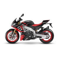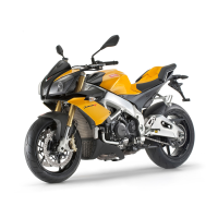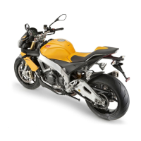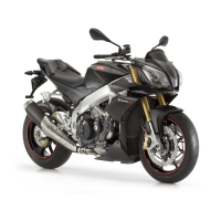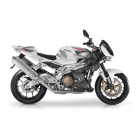
Do you have a question about the APRILIA Tuono V4 1100 Factory and is the answer not in the manual?
| Displacement | 1077 cc |
|---|---|
| Bore x Stroke | 81 x 52.3 mm |
| Compression Ratio | 13.6:1 |
| Transmission | 6-speed cassette type gearbox |
| Clutch | Multiplate wet clutch with mechanical slipper system |
| Rear Brakes | Single 220 mm disc, Brembo caliper |
| Front Tire | 120/70 ZR 17 |
| Width | 810 mm |
| Height | 1090 mm |
| Seat Height | 825 mm |
| Dry Weight | 185 kg |
| Engine Type | Aprilia V4 4-stroke, liquid cooled, double overhead camshaft (DOHC), four valves per cylinder |
| Max Power | 175 hp (129 kW) @ 11, 350 rpm |
| Max Torque | 121 Nm @ 9, 000 rpm |
| Fuel System | Electronic fuel injection |
| Exhaust | 4-2-1 system |
| Frame | Aluminum dual beam |
| Front Suspension | Öhlins NIX 43 mm fork, fully adjustable |
| Rear Suspension | Öhlins monoshock, fully adjustable |
| Front Brakes | Dual 330 mm discs, Brembo M50 monobloc calipers |
| ABS | Cornering ABS |
| Wheels | Aluminum alloy |
| Rear Tire | 200/55 ZR 17 |
| Fuel Tank Capacity | 18.5 L |
Checks to be performed before delivering the motorcycle.
Specific safety advice for handling hazardous substances and conditions.
List of special tools with stores codes and descriptions for engine support and containment.
Table detailing maintenance tasks and intervals in miles/kilometers for US-LATAM market.
Table detailing maintenance tasks and intervals in kilometers/months for Asia/Pacific market.
Diagram showing the location of various electrical components on the motorcycle.
Details on materials and quantities for electrical system installation and cable routing.
Importance of proper connection and tightening of security-locks for critical connectors.
Operations to perform before removing the engine, such as removing fuel tank and battery.
Step-by-step procedure for draining coolant and oil before engine removal.
Diagram of the engine with numbered key indicating cylinder locations.
The order and angles of cylinder firing in the engine.
Exploded view and torque specifications for gearbox components.
Steps for removing the gearbox selector, clutch housing, gear sensor, Seeger ring, and oil pump gear.
Procedure to remove the desmodromic gearbox control rod drum roller cage.
Characteristic wear limits for selector gear splines and shaft seats.
Procedures for removing and installing the starter motor.
Fuel system layout diagram with key for components like injectors, throttle bodies, and fuel tank.
Information on the fuel pump, its function, and layout.
Steps to remove the fuel pump, including disconnecting the tank and safety plate.
Section dedicated to the front suspension system.
Exploded view and torque specifications for front fork components (Ohlins ASC).
Exploded view and torque specifications for Sachs front fork components.
Information on standard and racing adjustments for front fork settings, including ASC mode.
Details on adjuster screws for rebound, compression, and spring preload on Sachs forks.
Recommended standard settings for rebound, compression, and spring preload for road use.
Settings for racing use, including rebound, compression, and spring preload adjustments.
Details on electronic adjustment for Ohlins forks with ASC system.
Step-by-step instructions to remove front fork stanchions, including disconnecting electrical components.
Exploded view and torque specifications for rear shock absorber components.
Procedure for adjusting rear shock absorber rebound, compression, and spring preload.
Exploded view and torque specifications for chassis mounting screws and couplings.
Exploded view and torque specifications for front wheel axle nut and brake disc screws.
Steps to remove the front wheel, including supporting the motorcycle and removing mudguard.
Procedures for checking front wheel bearings' rotation and play.
Exploded view of the rear wheel components.
Checks for rear wheel rim eccentricity and bearing condition.
Procedure for removing the rear sprocket support assembly.
Procedures for checking rear wheel bearings' rotation and play.
Exploded view and torque specifications for rear swingarm components.
Steps to remove the swingarm, including detaching brake caliper and front sprocket cover.
Torque specifications for ABS control unit mounting screws and oil tubes.
Diagram illustrating the ABS functional layout and key.
General specifications and stages of ABS operation, including brake activation and pressure reduction.
Foreword on ABS warning lights, system deactivation, and fault detection logic.
Diagram of the self-bleeding cooling system with key components identified.
Description of the cooling system components: pump, thermostat, radiator, fans, expansion tank.
Torque specifications for radiator and expansion tank mounting screws.
Torque specifications for water pump mounting screws.
Procedures for removing and installing the electric fan.
Steps for removing fairings, draining coolant, and removing the radiator cap.
Instructions for refilling the cooling system with coolant via radiator and expansion tank.
Procedures for removing and installing the tail fairing and passenger saddle.
Procedures for installing and removing the passenger saddle.
Steps to remove and install the rider saddle using a hex key and unscrewing fixing screws.
Procedure for removing and checking driving mirrors, applicable to both sides.
Steps to remove the instrument panel, including the brow and disconnecting connectors.
Procedure to remove the headlight unit, including fairings and connectors.
Procedure to remove the top fairing and its components.
Procedure to remove the lower steering yoke trim element.
Procedure to remove the tail light unit, including fairing and connector.
Steps to remove the license plate light, including screws and connectors.
Procedure to remove side fairings after removing rider saddle.
Steps to remove side fairings by unscrewing clips and screws.
Procedure to remove under-fairings, front fairing, front lock, and side fairings.
Procedure to remove the left hand under-fairing.
Procedure to remove the right hand under-fairing.
Procedure to remove the central under-fairing after removing side fairings.
Procedure to remove the front mudguard.
Procedure to remove the passenger handle, if applicable.
Procedure to remove the instrument panel cover.
