DESCRIPTION
The CV10 unit is an electronic board for the automation of doors, windows and gates with the help of electro-mechanic
actuators.
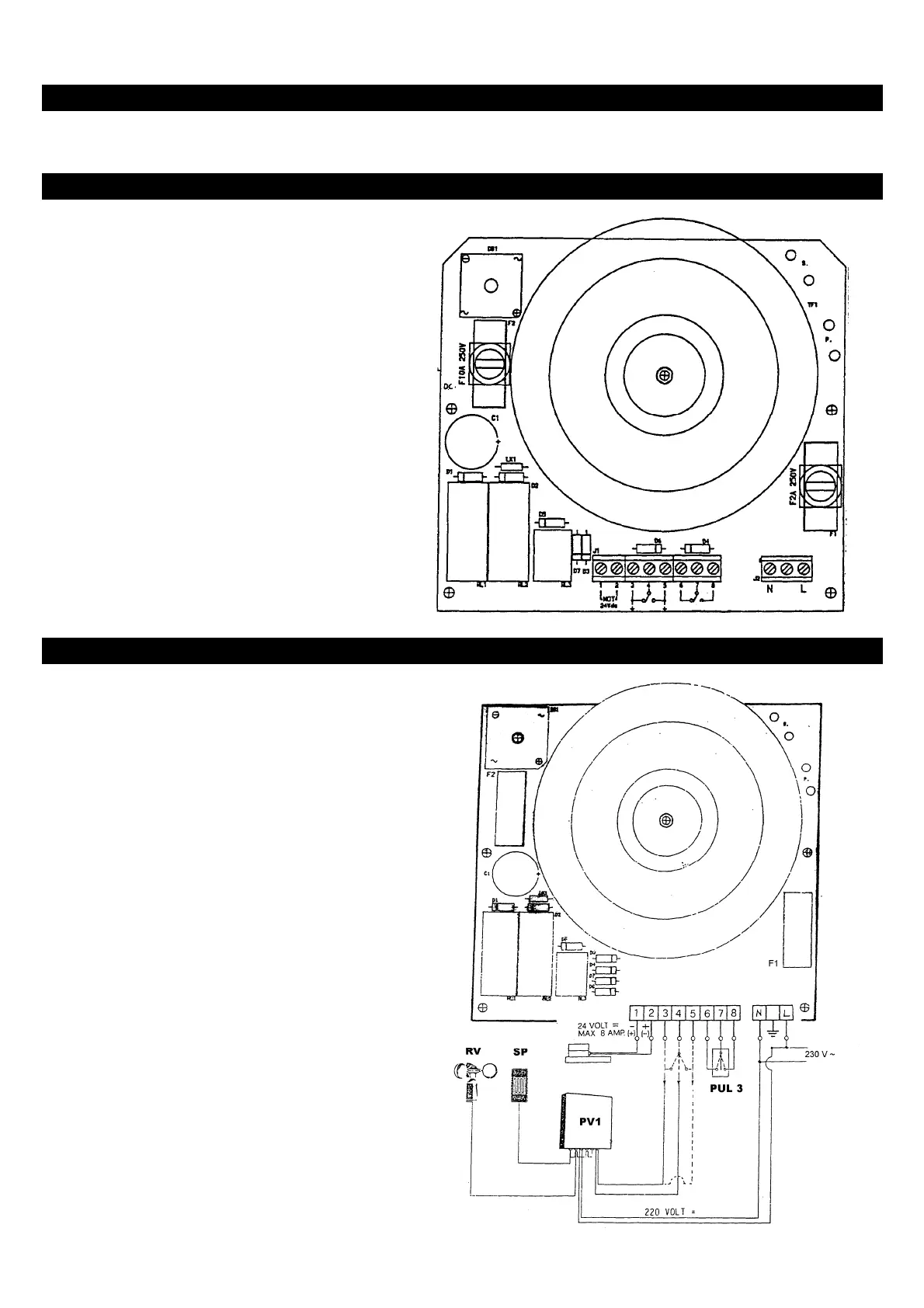
BLOCK DIAGRAM OF EQUIPMENT
F1 = 2A fuse for 230 V power supply
F2 = 10A fuse for 24 V power supply
J1 = Control and drive terminal board
J2 = 230 V power supply terminal board
TF1 = Transformer
RL1-RL2 = Open/close switch relay
RL3 = Drive priority management relay
DB1 = 10 A rectifier bridge
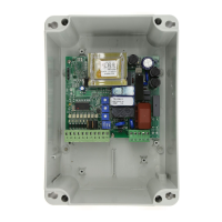
CV10 TERMINAL BOARD DESCRIPTION
1 Terminals 1 and 2: power supply for the
actuators. Connection for supplying power to
24Vdc actuators with maximum absorption of
8A.
2 Terminals 3, 4 and 5: open/close command
(local). Contact for commanding opening and
closing of the actuator. The operation of this
contact has priority over terminals 6, 7 and 8.
3 Terminals 6, 7 and 8: open/close command
(local). Contact for commanding opening and
closing of the actuator without any priority. When
the centralised contact is enabled, every function
is disabled and is re-enabled only when the
centralised contact is in the rest position.
4 Terminals N and L: 230 V, 50 Hz power supply.
L = PHASE
N = NEUTRAL
N.B. Connect PV1 to either "3 and 4" or to "4 and
5" as required, making sure that the
emergency rain-wind gives the closing
command.