18 www.Aprimatic.it
7.6 ELECTRICAL CONNECTION OF SAFETY SENSOR
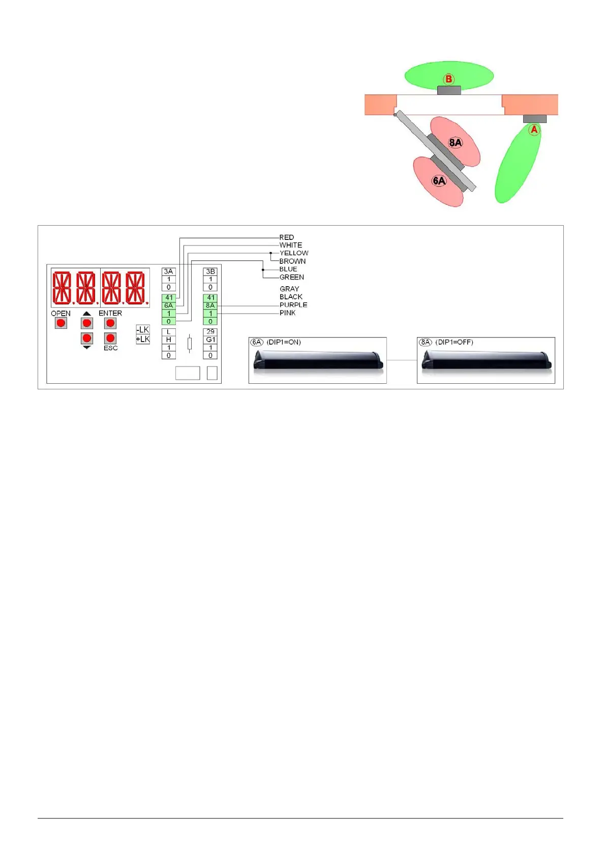
The safety sensors should be installed directly on the door swing, and
protect both the opening and the closing of the door swing.
If you install two sensors, they are connected to each other via the
supplied cable, and only one of them is connected to the terminals of the
electronic control as shown below.
For more information, check the installation manual of the sensor.
6A SENSOR (WITH DIP1=ON)
Connecting the safety opening sensor 6A (set DIP1=ON)
of the swing door.
green wire = terminal 0
blue wire = terminal 0
brown wire = terminal 1
yellow wire = terminal 1
white wire = 6A terminal (remove the jumper 41‐6A)
red wire = terminal 41
pink wire = do not connect
purple wire = do not connect
gray wire = do not connect
black wire = do not connect
8A SENSOR (WITH DIP1=OFF)
Connecting the safety closing sensor 8A (set DIP1=OFF) of
the swing door.
green wire = terminal 0
blue wire = terminal 0
brown wire = terminal 1
pink wire = terminal 1
purple wire = 8A terminal (remove the jumper 41‐8A)
red wire = terminal 41
yellow wire = do not connect
white wire = do not connect
gray wire = do not connect
black wire = do not connect
6A SENSOR (WITH DIP1=ON) + 8A SENSOR (WITH DIP1=OFF)
Connection of 2 safety sensors for opening 6A (set DIP1=ON)
and closing 8A (set DIP1=OFF) of the swing door.
green wire = terminal 0
blue wire = terminal 0
brown wire = terminal 1
yellow wire = terminal 1
white wire = 6A terminal (remove the jumper 41‐6A)
red wire = terminal 41
pink wire = terminal 1
purple wire = 8A terminal (remove the jumper 41‐8A)
gray wire = do not connect
black wire = do not connect
 Loading...