PAGE 5
©2018 4Front Engineered Solutions, Inc. - APS Resource
AP6846J 8/18
4. Carefully lift the fan assembly, locating the mounting
pin through the arm assembly. It is recommended
that two people lift the fan to the arm.
5. If mounting a docklight head to the TURBO-ES Fan
and arm assembly, please skip to the next section
labeled “MOUNTING DOCKLIGHT HEAD TO
TURBO-ES FAN ARM ASSEMBLY (OPTIONAL)”.
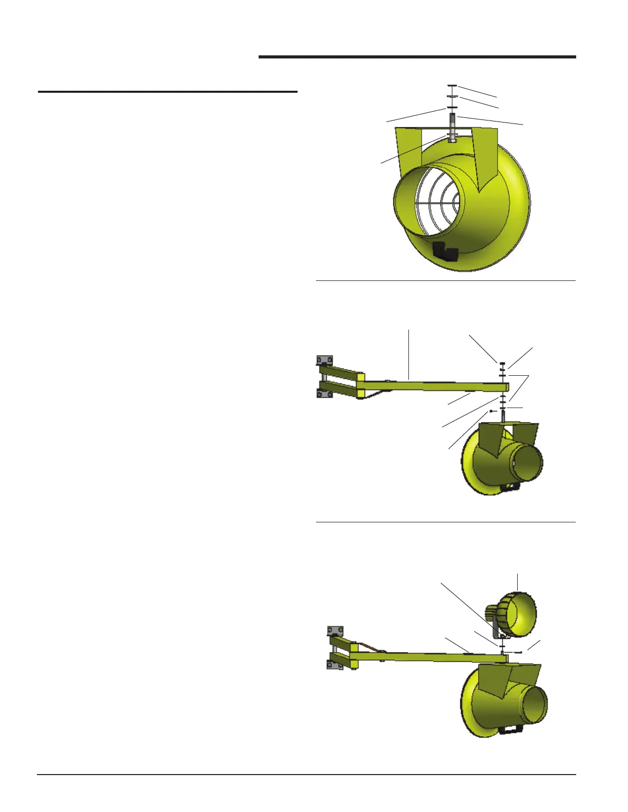
6. After the mounting pin is through the arm, install (1)
at washer, (1) lock washer and (1) slotted lock nut
as shown in FIGURE 2.
7. Tighten the slotted lock nut to obtain the desired
amount of resistance when rotating the TURBO-ES
Fan. If less resistance is desired, remove the star
washer.
8. Install the cotter pin through the slots in the locknut
and hole in the mounting pin. Bend the cotter pin to
secure it in place.
9. Route the power cord along the arm assembly,
and secure to the arm assembly. Ensure that the
power cord will not interfere with the operation and
movement of the arm.
10. Plug the power cord into an electrical outlet.
11. Check the nal assembly for safe operation.
MOUNTING DOCKLIGHT HEAD TO TURBO-
ES FAN ARM ASSEMBLY (OPTIONAL)
1. After the mounting pin is through the arm, install (1)
lock washer, the docklight head, and (1) slotted lock
nut as shown in FIGURE 3.
2. Tighten the slotted lock nut to obtain the desired
amount of resistance when rotating the TURBO-ES
Fan. If less resistance is desired, remove the star
washer.
3. Install the cotter pin through the slots in the locknut
and hole in the mounting pin. Bend the cotter pin to
secure it in place.
4. Route the power cord along the arm assembly,
and secure to the arm assembly. Ensure that the
power cord will not interfere with the operation and
movement of the arm.
5. Plug the power cord into an electrical outlet.
6. Check the nal assembly for safe operation.
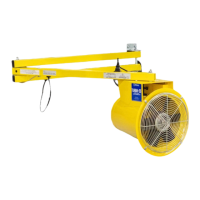
INSTALLATION
FIGURE 2
INSTALLATION (cont.)
FIGURE 3
MOUNTING
PIN
METAL/RUBBER
WASHER
(RUBBER SIDE DOWN)
FIGURE 1
STAR WASHER
FLAT WASHER
FLAT WASHER
LOCK WASHER
COTTER PIN
(INSTALL LAST)
STAR WASHER
FLAT WASHER
ARM ASSEMBLY
SLOTTED LOCK NUT
METAL/RUBBER
WASHER
(RUBBER SIDE DOWN)
RECEPTACLE
LOCK
WASHER
COTTER PIN
(INSTALL LAST)
SLOTTED LOCK NUT
DOCKLIGHT HEAD
(OPTIONAL)
RECEPTACLE
 Loading...