PAGE 5
5609 RS 01/17
©2017 4Front Engineered Solutions, Inc. - APS Resource
1
1
2
2
3
3
4
4
A A
B B
C C
D D
- CRITICAL QUALITY DIMENSION
TOLERANCES ARE IN INCHES
UNLESS OTHERWISE SPECIFIED
MATERIAL SPECIFICATION
DRAWN
MATERIAL#/PO#
PART DESCRIPTION
DRAWN DATE
JOB/REF NUMBERSCALE
ISSUEPART NUMBER
.X :
0.060
.XX :
0.030
.XXX :
0.010
FRACTIONAL :
1/16
DIAMETER : +0.015 / -0.005
ANGULAR :
1 DEG
AFORM5609-FIG2&6
APS 2000 SUB-ASSEMBLY
NONE
JJS 2/29/2012
UOM
INCH
The information contained herein is proprietary and confidential to 4Front Engineered Solutions, Inc. - APS Resource and is to be
used solely for the express purpose of consideration and development of the article described herein and may not be reproduced or
disseminated without the express written permission of 4Front Engineered Solutions, Inc. - APS Resource.
SHEET SHEET SIZE
C1 OF1
Your After market S olution
APS Resource
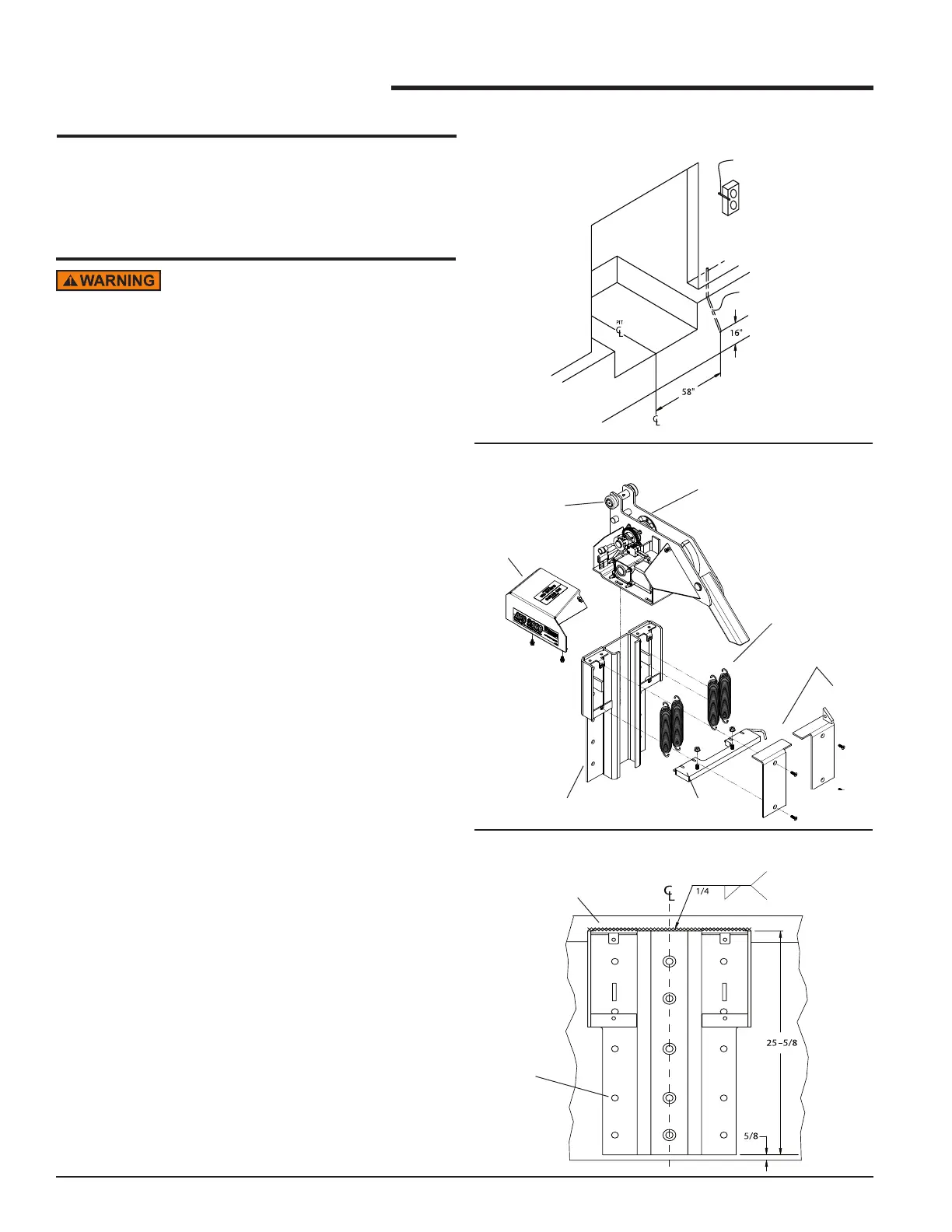
CONDUIT INSTALLATION
1. When installing conduit through building walls and
oors, refer to Figure 1 for reference dimensions.
SEE FIGURES 7 & 9 FOR
LOCATION OF THE CONTROL
BOX AND OUTSIDE SIGNAL
LIGHT.
USE 1/2” DIAMETER
CONDUIT THROUGH
WALL TO OUTSIDE
SIGNAL LIGHT.
EXIT CONDUIT INSIDE
BUILDING NEAR WALL
UNDER CONTROL BOX.
USE 1” DIAMETER
CONDUIT FOR RUN
TO RESTRAINT.
FIGURE 1
FIGURE 2
FIGURE 3
1. Remove the carriage assembly from the roller track
prior to installation. First, remove the motor cover and
spring covers. Then remove springs and nuts from
spring bar. Slide carriage assembly upwards out of
the roller track, making sure to keep the rollers on the
axles. See Figure 2.
2. Place bottom edge of the roller track plate a
maximum of 5/8" above the driveway and center with
the pit. See Figure 3. If the driveway is susceptible
to heaving from frost, ensure adequate clearance
under the APS 2000
®
to prevent damage from the
driveway movement.
3. Drill 5/8" dia holes into pit wall a minimum of 4-5/8"
deep using holes in roller track as a guide.
FRONT PIT
CURB ANGLE
ALL 15
HOLES
MUST BE
ANCHORED
MOTOR
COVER
ROLLER
CARRIAGE ASSEMBLY
ROLLER TRACK
SPRING BAR
SPRING
SPRING COVERS
CONTINUOUS
WELD ON TOP
EDGE
INSTALLATION
Do not install, operate, or service this product unless
you have read and followed the Safety Practices,
Warnings, and Installation and Operating Instructions
contained in this manual. Failure to do so could
result in death or serious injury. ALWAYS USE
DOCKLEVELER SUPPORT WHEN WORKING UNDER
A DOCK LEVELER RAMP OR LIP.
Place barricades around the pit on the dock oor and
driveway while installing, maintaining or repairing
dockleveler or vehicle restraint.
Improper installation of anchoring devices or
installation into aged or unsound concrete could
result in death or serious injury.
Inadequate lifting equipment or practices can cause a
load to fall unexpectedly. Make sure the lifting chain
or other lifting devices are in good condition and
have a rated capacity of at least 500 lbs for the lifting
angle used. Never allow anyone to stand on or near
the restraint when it is lifted or positioned. Stand
clear of the vehicle restraint when it is positioned.
Failure to follow this warning can allow the restraint
to fall, tip, or swing into people, causing death or
serious injury.
INSTALLATION WITH
PIT TYPE DOCKLEVELERS
 Loading...