U:\Affaires\Aqua-Base\ESW\09- Manuels Utilisateur\DOC UTILISATEUR ESW FRUKES 2023-06-Y3.doc
VERSION 2023-06-Y3
FR/UK/ES
Page 19/52
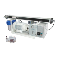
3 – DESCRIPTION
3.1 – WATER SYSTEM – FLOW CHART
In the basic version, desalinator ESW is made up of the following elements:
REP. DESCRIPTION FUNCTION
:
Minimal
Ø3/4"
it ensures continuous seawater feeding of the unit
supplies.Do not take water from the motor’s cooling system. Place the hull valve (V0) as far away as possible
from the rejected brine hull fitting (R).
e hull fitting, it ensures the closing of the seawater intake
A1/A2/A5
Feeding pipes
to the unit through the filter
reinforcement A1/A2/A5) and internal diameter 19 (flexible B1/B2).
1 Inlet valve
chemical solution contained in a bucket during cleaning or preservation of the membrane.
Small screen filter ensuring seawater filtering of la
28 Vaccum switch
If the pump cavitation become
the unit is stopped to avoid damage to the mechanical and paddles pump.
en by an electric motor, it ra
ises seawater pressure to the required value between
below the water line.
Contains a filter cartridge ensuring seawater filtering of particles gre
membrane).
Indicates the LP pressure.
Increases seawater pressure to produce fres
h water through the R/O membrane
To bleed the system at the fir
ent of the filters. Allows ope
ration of the unit at low pressure when
opened for cleaning or preservation operations.
Indicates the HP pressure
s, containing the membrane
which the desalination of
11 Cleaning valve
By opening this valve, the valve (1) i
position, the unit can be ope
auxiliary tank (or bucket) containing the cleaning solution.
14 Valve 3-way
way valve controlled by the salinity cell. It automatically directs the
the salinity is correct, or towards the discharge to the sea, if it isn’t.
15 Activated carbon
esh rinsing water to preserve the membrane.
water, and controls the valve
(14) according to this measurement.
Ensures automatic rinsing of the desalina
tor by using fresh water from the boat’s water circuit under pressure.
d brine produced by the membra
ne for discharge to the sea.
be 19.
C1 Vaccum switch fitting
booster pump (red hose 4x6).
R Hull fitting
luded in the supplies (avoid installing the
reject fitting in front of the seawater entry hull fitting).
Ensures supply of fresh water and chemical solutions stored in a buc
storage operations. Ensures the cleaning of the membranes in a closed loop by opening the valve 11. Imperative internal
diameter must be 20 (Embedded steel spirale reinforcement A3) and internal diameter must be 19 (flexible B4).
A4 / A6 Rinsing pipe
pply of fresh water from the fresh water tank, during
rinsing electrovalve (18). Internal diameter must be 20 (Embedded steel spirale reinforcement.
 Loading...