LEAKSHIELD
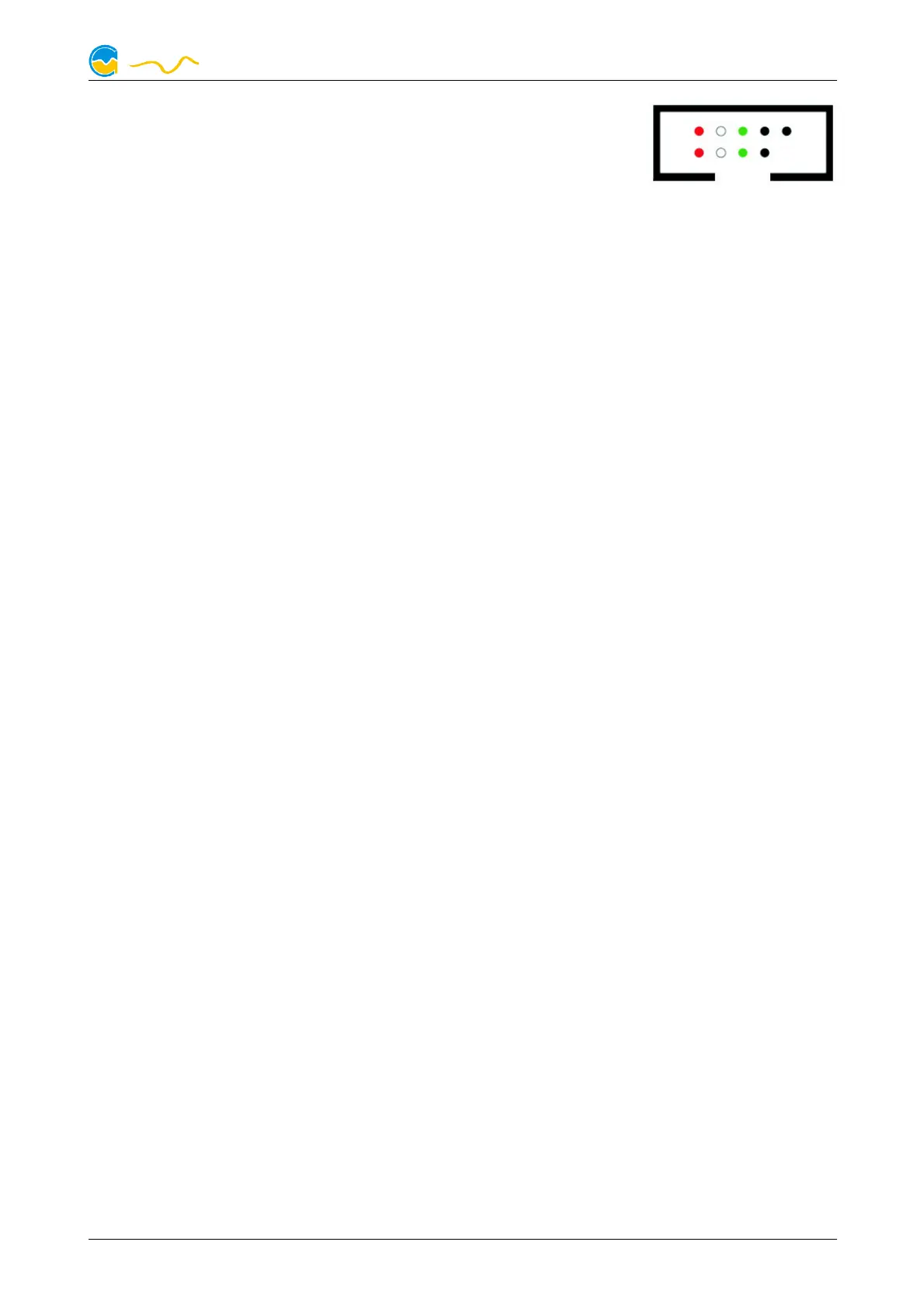
The corresponding connector on the motherboard is usually
a 9 pin connector with two independent USB ports. Both
rows of 4/5 pins can be used to connect an USB device.
The black wires (GND) are to be connected to the side of
the missing pin, see picture with colored pin assignment.
6.2.
6.2.6.2.
6.2. Connector “signal”
Connector “signal”Connector “signal”
Connector “signal”
The header can be connected to the power switch header of the motherboard us-
ing an additional specialized cable (53216, not included in delivery).
Pin assignment: Pin 1: GND
Pin 2: not connected
Pin 3: open drain max 3.3 V / 5 mA
In the event of an alarm, this interface can be used to shut down the computer in
the same way as pressing the power button. A short or long press can be config-
ured.
7.
7.7.
7. Operation on the device
Operation on the deviceOperation on the device
Operation on the device
The most important functions of LEAKSHIELD can be controlled directly on the de-
vice. A button located at the right side of the LEAKSHIELD silicone illuminated ring
is used to control the menu.
By a short press on the button, it is possible to navigate directly through the display
pages.
If the button is pressed for longer than one second, the menu is displayed.
At this moment, "MENU" appears briefly in the display, followed by the menu
items.
By shortly pressing the key, you can now select between the following items:
SHIELD (mode selection)
SHIELD (mode selection)SHIELD (mode selection)
SHIELD (mode selection)
Complete protection and detection of leakages. This function can only be used re-
liably after a configuration via the aquasuite!
MONITOR (mode selection)
MONITOR (mode selection)MONITOR (mode selection)
MONITOR (mode selection)
The system is monitored for leaks by using a low negative pressure. There is no
protection against leakage in this mode.
RELEASE (mode selection)
RELEASE (mode selection)RELEASE (mode selection)
RELEASE (mode selection)
© 2021 Aqua Computer GmbH & Co. KG - 7 -
Gelliehäuser Str. 1, 37130 Gleichen