6
Filter Setup
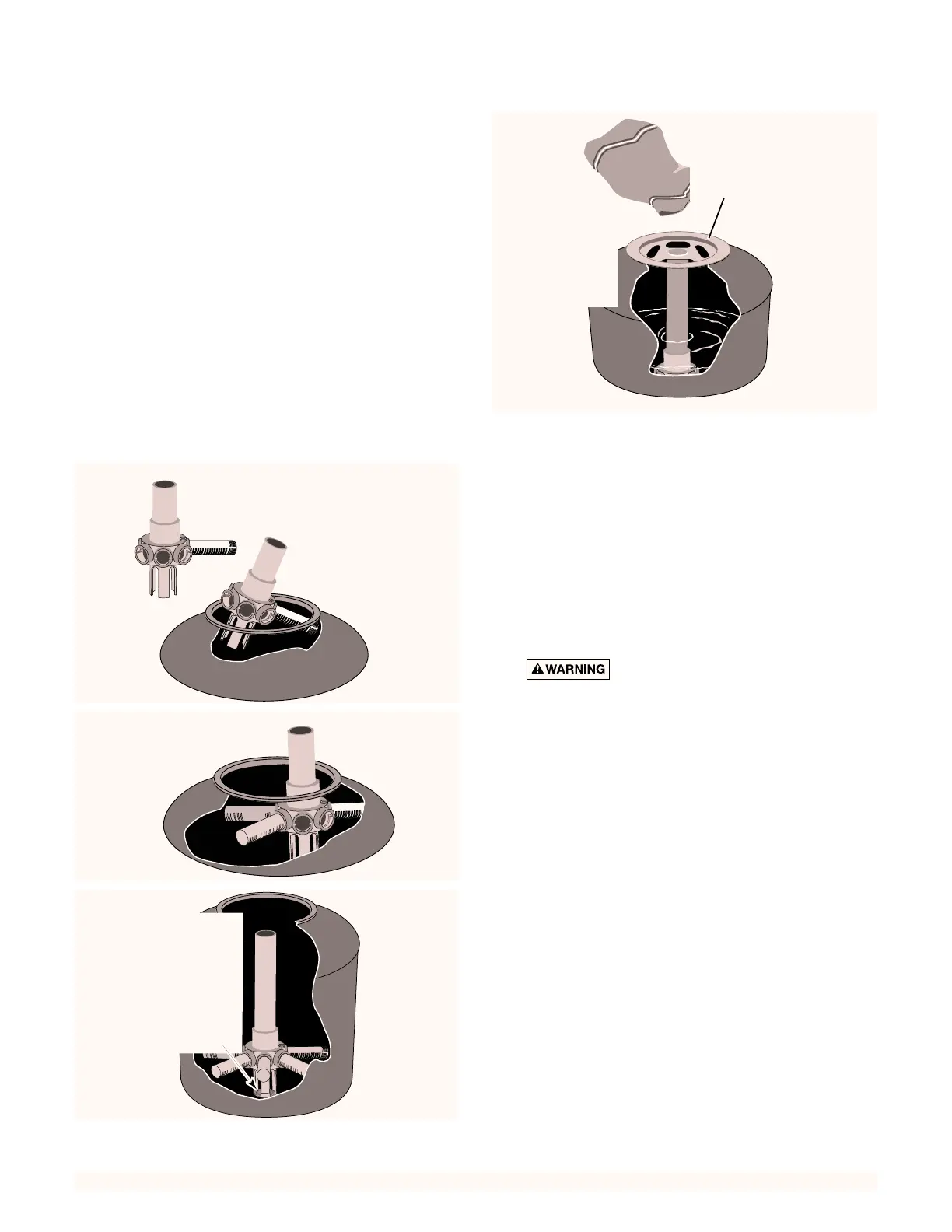
Assembly: See Figures 2 through 5 for filter assembly.
Loading Sand Media
1. To keep sand out of collector assembly, place plastic
sand shield over top of collector tube before pouring
sand into filter (See Figure 5).
2. To support laterals and prevent lateral breakage dur-
ing loading, fill tank about half full of water before
loading sand.
3. Pour sand into filter tank. See “Recommended Sand
Grades”, Page 4, for correct type and quantity of sand
to use.
NOTICE: Make sure gasket area on top of tank is free
of sand before installing valve and clamp.
4. Before installing valve, double-check that correct
quantity of sand has been loaded (see Page 4).
5. Remove plastic sand loading shield and keep for fu-
ture use.
Valve Installation:
See Figures 6, 7, and 8
1. Install O-Ring on valve flange; make sure O-Ring is
clean, dry, and has no nicks, tears, or scrapes.
2. Make sure tank and valve flanges are clean and free
of sand; put valve on top of tank. Vertical pipe of
collector assembly inserts into base of valve.
3. Install clamp; make sure knob is positioned for easy
access for filter maintenance. Valve port labeled
“PUMP” must align with pump discharge port.
4. Tighten clamp knob until clamp ends (under bolt)
are 1/4” (6mm) apart. Tap around outside of clamp
with a mallet to help seat clamp.
Hazardous pressure. Clamp will not
hold unless it is seated properly! DO NOT START
PUMP until clamp ends are 1/4” (6mm) apart or
less.
5. If clamp will not pull up to 1/4” (6mm) gap, wait
15-30 minutes and retighten. Tap clamp gently with
mallet to help seat clamp.
6. Tape hose fitting threads with 2-3 turns of teflon
tape; install hose fittings in valve “PUMP” port and
in pump discharge port. See Figure 8.
7. Lubricate both ends of connecting hose sparingly
with dish soap or petroleum jelly. See Figure 9.
8A. Push hose onto barbed fitting in valve port until it
butts against octagonal ring. Slide 2 hose clamps
onto hose. See Figure 10.
8B. Tighten hose clamp at valve port on shank of hose
barb (
not
on ridges).
9A. Push hose onto barbed fitting in pump discharge
port until it butts against octagonal ring. See
Figure 11.
9B. Tighten hose clamp at valve port on shank of hose
barb (
not
on ridges).
B. Insert assembly
filter tank.
A. Insert first lateral into socket;
to lock lateral into hub.
when slots face down.
C. Hold assembly up
laterals.
D. After all
tank.
sand.
loading filter.
 Loading...