
K
Kayla ThompsonAug 18, 2025
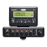
Why is the displayed speed not precise on my ARAG Bravo 180S?
- TTheresa SmithAug 19, 2025
If the displayed speed on your ARAG Farm Equipment is not precise, it might be due to a wrong setup. Check the setup of the wheel constant.