
M
Mary GrayJul 31, 2025
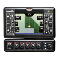
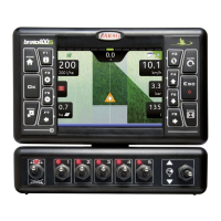
What to do if ARAG Bravo 400S LT display does not switch on?
- AAlicia MartinezJul 31, 2025
If the ARAG GPS display doesn't switch on, there could be a couple of reasons. First, check the power supply connection to ensure it is properly connected. If the power supply is fine, make sure the computer is turned on by pressing the ON key.