EasyManua.ls Logo

Arcam Alpha 8 - User Manual

Arcam Alpha 8
17 pages
Print Icon
To Next Page IconTo Next Page
Loading...
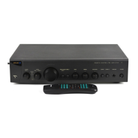
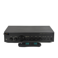
ALPHA 7/8/9 CD SERVICE MANUALALPHA 7/8/9 CD SERVICE MANUAL
Arcam Alpha 7/8/9 CD Service Manual
Issue 1 Serial No. 0001 - (Paul Newton July 96)
Circuit Description
The following notes describe the operation of the
Alpha 7/8/9 CD players. They include the circuitry on
the main, DAC and display PCBs but not that on the
servo PCB attached to the mechanism.
Power Supplies
The mains input is fitted with inductors L2,3,6,7 to
filter electromagnetic interference coming out of the
player.
Mains transformer T201 has three secondary
windings supplying two separate power supplies and
an AC supply for the display filament:
Analogue Supply
Bridge rectifier D4,5,6,7 and reservoir capacitors
C209-C212 produce unregulated split rails of about
+/-22V.
Z204 and Z205 provide regulated outputs of +18V
and -18V respectively that power the opamps in the
audio output stage.
Since there is no power switch on this secondary, the
analogue supplies are always connected.
Digital Supply
Switch SW201-A disconnects the digital secondary
winding when the 'Power' switch is out.
An unregulated supply of about 11V is produced by
the bridge rectifier D8,9,10,11 and reservoir
capacitor C36.
This is then regulated to provide three +5 volt
supplies (Z208 general logic supply, Z207 DAC
supply, Z203 system clock generator supply) and a
+7.3v supply for themechanism and motor drive
circuits(Z206).
A -30v supply is formed by Z209 and associated
components to power the display grid.
Muting
When the unit is turned off SW201-A discharges
capacitor C29 quickly. This along with the AMUTE
signal from the microprocessor, controls the output
mute transistors Q1,101 via level shifter Q3.
Clock Generator
The system clock is generated by a discrete oscillator
based around Q2 and 16.9344MHz oscillator X1. The
output of Q2 is amplified and buffered by inverters
Z202-E & D and sent to the clock input of the DAC
Z201.
DAC & Audio Outputs (Alpha 7 only)
The DAC is a Delta-Sigma design from Burr Brown,
the PCM1710U.
The serial digital data from the decoder Z206 is input
to pins 1 to 3. The system clock is input to pin 5.
The DAC is powered entirely from one 5V supply,
although it is split and decoupled between the
analogue and digital sections of the device.
The analogue outputs from each channel are
processed identically.Three poles of filtering are
provided by the active filter based around Z1-A. Z1-B
buffers the audio output and sets the output level.
Muting is provided by turning on Q1 and Q101.
DAC & Audio Outputs (Alpha 8 only)
This is a similar circuit as the one used on the Arcam
Alpha 6 DAC PCB but designed for Sony format
input data and a better digital filter, the SM5843AP1,
Z14.The digital filter is used with a SM5864AP 20-bit
DAC chip, Z12, (described here as a PWM noise
shaper to avoid confusion with the 1-bit DAC Latch
which follows it). The output from this is re-latched by
Z7, Z8.
Digital FilterA PIC micro on the mother board
controls the filter with the signals RB0 to RB7. The
SM5843 filter has internal pull-up resistors on its
inputs resulting in RB4 & RB5 being logic 1.
The SM5843APT requires several control lines from
the PIC...
RB7 FSEL2, Selects sampling rate for de-emphasis.
Static low for 44.1K.
RB6 FSEL1, Selects sampling rate for de-emphasis.
Static low for 44.1K.
RB5 IW2N, Selects input word length. Static high for
16 bits.
RB4 MDT, Serial data input for volume control. Burst
at switch-on for setting to full.
RB3 RSTN, Reset line. Short pulse low at switch on,
then static high.
RB2 MLEN, Serial data latch input for volume
control.
RB1 MCK, Serial clock input for volume control.
RB0 Not connected.
No Dither On Silence
The digital filter adds ‘dither’ to the output signal.
This improves the low-level performance of the DAC.
The PWM filter normally mutes when it detects
digital silence to prevent any unwanted noise and
idle-tones on the audio outputs when no music is
playing. A slight click is audible when this happens.
Unfortunately, the added dither prevents this mute
from operating because it holds it open. Q11 detects
digital silence on the data input to the filter. When
silence is detected, the dither function is switched off

Other manuals for Arcam Alpha 8

Question and Answer IconNeed help?

Do you have a question about the Arcam Alpha 8 and is the answer not in the manual?

Summary

Circuit Description

Power Supplies

Details the analogue and digital power supply circuits, including unregulated and regulated rails.

DAC and Audio Output Stages

Describes the DAC and analogue output stages for Alpha 7 and Alpha 8 models.

Digital Filter Dither

Explains the dither function for low-level performance and its effect on the silence mute.

Mute Relay Operation

PWM Noise Shaper Details

Explains clock signal amplification for the PWM noise shaper chip.

Latch and Analogue Filter Stages

Describes re-latching PWM data and the multi-stage analogue filtering process.

Test Points Overview

Disc Transport Module

Digital Signal Processor

Explains mute, attenuation, and de-emphasis control via serial bus.

System Controller Function

Details the CXP826P16Q system controller functions and remote input.

Disassembly Procedures

Provides step-by-step instructions for disassembling the CD player.

Non-PCB Parts and Metalwork

Main PCB Component Layout

Alpha 8 DAC PCB Layout (Underside)

Alpha 8 DAC PCB Layout (Top View)

System Connectivity and Documentation

Main Circuit Diagram

Configuration and Flex Connectors

CDM14 Flex Connector Interface

Details the signals and pins of the flex connector from the CDM14 mechanism.

DAC Data Connector Interface

Explains the data interface signals between the main board and the DAC PCB.

Display PCB Circuitry

System Controller Interface

Shows the interface between the system controller (CXP826P16Q) and the display.

Button and LED Control

Details connections for front panel buttons, display driver, and LEDs.

Overview

The Arcam Alpha 7/8/9 CD player is a high-fidelity audio component designed for playing compact discs. This service manual provides detailed information on its circuitry, technical specifications, usage, and maintenance.

Function Description

The Alpha 7/8/9 CD player's core function is to accurately read and convert digital audio data from compact discs into an analogue audio signal for playback through an audio system. It incorporates several key modules to achieve this:

  • Disc Transport Module: This module, based on the CDM 14 mechanism, handles disc loading, laser tracking, RF amplification, and analogue signal processing. It also includes all servo control and motor drive circuits necessary for precise disc rotation and laser positioning.
  • Digital Signal Processor (DSP): The DSP manages mute, attenuation, and de-emphasis functions, controlled via a three-wire serial bus from the system controller. It receives digital audio in Sony format (Word Clock, Data, and Bit Clock) and generates a digital output complying with the SPDIF standard, which is passed through an isolating transformer to the digital output socket.
  • System Controller: The CXP826P16Q system controller (Z212) acts as the central brain, combining CD player control, keyboard scanning, remote control decoding, and fluorescent display driving. It operates with a 4.00MHz resonator (X201). The controller detects the disc drawer's position via microswitches and controls the drawer motor. Keyboard scanning is achieved by connecting keys to a resistor ladder on an ADC input, presenting a unique voltage for each key press. Remote control signals, after passing through a PIC microcontroller (Z211) that converts RC-5 format codes to NEC data, are used to configure the digital filter/DAC on Alpha 8 and 9 DAC boards.
  • Power Supplies: The unit features a robust power supply system. Mains input is filtered for electromagnetic interference. A mains transformer (T201) provides three secondary windings:
    • Analogue Supply: A bridge rectifier and reservoir capacitors produce unregulated split rails of approximately +/-22V. These are then regulated to +18V and -18V by Z204 and Z205, powering the op-amps in the audio output stage. This supply is always connected.
    • Digital Supply: A switch (SW201-A) disconnects the digital secondary winding when the 'Power' switch is off. An unregulated 11V supply is generated by a bridge rectifier and reservoir capacitor (C36), then regulated to provide three +5V supplies (Z208 for general logic, Z207 for DAC, Z203 for system clock generator) and a +7.3V supply for the mechanism and motor drive circuits (Z206).
    • A -30V supply is formed by Z209 and associated components to power the display grid.
  • Clock Generator: A discrete oscillator (Q2 and 16.9344MHz oscillator X1) generates the system clock. Its output is amplified and buffered by inverters (Z202-E & D) and sent to the DAC's clock input.
  • DAC & Audio Outputs (Alpha 7 only): The Alpha 7 uses a Burr Brown PCM1710U Delta-Sigma DAC (Z201). Serial digital data from the decoder (Z206) is input to pins 1-3, and the system clock to pin 5. The DAC is powered by a single 5V supply, split and decoupled for analogue and digital sections. Analogue outputs are processed by an active filter (Z1-A) providing three poles of filtering. Z1-B buffers the audio output and sets the output level. Muting is controlled by transistors Q1 and Q101.
  • DAC & Audio Outputs (Alpha 8 only): The Alpha 8 employs a Sony format digital filter (SM5843AP1, Z14) and a SM5864AP 20-bit DAC chip (Z12), which functions as a PWM noise shaper. The output is re-latched by Z7 and Z8. A PIC micro on the motherboard controls the filter via signals RB0-RB7. The SM5843 filter has internal pull-up resistors, resulting in RB4 & RB5 being logic 1.
    • PWM Noise Shaper: To reduce EMC, the clock signal to Z12 (XTI pin 23) is weak and amplified to provide a larger signal on the CKO pin (26). The PWM output on pins 11, 13, 16, and 18 can be resolved into an audio waveform using a scope and a 100K resistor.
    • Latch: PWM data from Z12 is re-latched using 74HC74 latches (Z7 and Z8). These chips are powered by the DAC voltage reference, and their output drives the analogue filter stage directly, reducing edge-timing jitter.
    • Analogue Filter: The first half of the analogue filter (Z3 and Z4) is balanced, with signals on pin 1 and pin 7 of the op-amp being phase-inverted. Z1 and Z2 further filter the audio and convert the balanced signal to a single-ended signal. Z18 acts as a DC servo to reduce output offset voltage, which can be high initially but settles to less than 3mV after 10 minutes.
    • No Dither On Silence Feature: The digital filter normally adds 'dither' to improve low-level DAC performance. However, this can prevent the PWM filter from muting during digital silence, causing a slight click. Q11 detects digital silence at the filter's data input and switches off the dither function, allowing the PWM filter's mute to operate normally.

Important Technical Specifications

  • Clock Output: 16.9344MHz +/- 40ppm, 4V to 5V peak-to-peak square wave.
  • Analogue Supply: Regulated +/-18V d.c. +/- 0.5V.
  • Digital Filter Supply: Regulated +5V d.c. +/- 0.3V.
  • PWM Noise Shaper Supply: Regulated +5V d.c. +/- 0.3V.
  • Clock Supply: Regulated +5V d.c. +/- 0.3V.
  • DAC Reference Voltage: +5V +/- 0.3V.
  • Mute Relay Voltage: Equal to RLYPWR voltage when output is muted (0V d.c. +0.5V,-0.0V when un-muted).
  • System Clock for Latches: 4V to 5V peak-to-peak square wave at 16.9344MHz.
  • Audio Output DC Offset: Less than 3mV after 10 minutes.

Usage Features

  • Power Control: The analogue supplies are always connected. The digital secondary winding is disconnected by SW201-A when the 'Power' switch is off.
  • Muting: Output mute transistors (Q1, Q101) are controlled by SW201-A and the AMUTE signal from the microprocessor. A mute relay, controlled by the PIC micro via RA0, engages after a short settling delay when the unit comes out of standby mode.
  • Remote Control: The unit supports remote control via an RC-5 format converted to NEC data by a PIC microcontroller (Z211).
  • Display: A fluorescent display (DISP301) is driven by the system controller.
  • De-emphasis: Selectable via the DEEM input on SK203 (0V=off, 5V=On).
  • Input Word Length (Alpha 8 only): Selectable via RB5 IW2N (static high for 16 bits).
  • Sampling Rate (Alpha 8 only): Selectable via RB7 FSEL2 and RB6 FSEL1 (static low for 44.1K).
  • Volume Control (Alpha 8 only): Serial data input for volume control (RB4 MDT), bursts at switch-on to set to full.

Maintenance Features

  • Disassembly for Servicing:
    1. Remove the top cover.
    2. Eject the CD tray.
    3. Unplug the unit from the mains.
    4. Manually push the tray front upwards to remove it.
    5. Remove 4 screws holding the front panel and release locating tabs.
    6. Unplug the flexfoil from the display board.
    7. Remove 2 screws holding the remote receiver PCB.
    8. Pull off the front panel.
    9. Remove 6 screws holding the display PCB.
    10. To remove the main PCB, first remove the DAC board (if Alpha 8 or 9):
      • Remove 3 screws holding audio output sockets to the rear panel and 2 screws holding the aluminium extrusion.
      • Squeeze the tops of the 2 PCB pillars and lift the board.
      • Remove 2 flexfoils from the DAC board.
      • The DAC board, still attached to the extrusion, can now be removed.
    11. To remove the main PCB:
      • Remove 8 PCB securing screws and the screw holding the digital output socket.
      • (On Alpha 7 CDs, also remove 3 screws securing audio output sockets).
      • Release cables connecting the mechanism to the main board.
      • Slide the main PCB out of the case.
  • Test Points: Various test points are marked on the circuit diagram for measurement, including clock output, ground points, mute inputs, serial data inputs, regulated supplies, DAC reference voltages, and servo voltages. These are crucial for diagnostics and troubleshooting.
  • Reset Line (Alpha 8 only): RB3 RSTN provides a short pulse low at switch-on, then static high.
  • Serial Data Latch Input (Alpha 8 only): RB2 MLEN.
  • Serial Clock Input (Alpha 8 only): RB1 MCK.

Arcam Alpha 8 Specifications

General IconGeneral
BrandArcam
ModelAlpha 8
CategoryAmplifier
LanguageEnglish

Related product manuals