Do you have a question about the Arcomed Volumed uVP7000 and is the answer not in the manual?
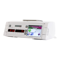
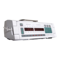
Overview of the Volumed µVP7000 pump and its applications.
Instructions for safe and stable positioning of the infusion pump.
Procedures and precautions for cleaning and disinfecting the infusion pump.
Guidelines for annual safety checks, including battery testing.
Explanation of pictograms and symbols used on the pump.
Compliance mark and medical device classification (Class IIb).
Specifies the minimum and maximum infusion rates and volumes.
Details on flow rate accuracy and maximum overinfusion volume.
Specifications for Keep-Vein-Open and bolus infusion rates.
Minimum, maximum, and alarm pressure settings.
Time delay before occlusion alarm is triggered.
Range and sensitivity of the air detection system.
Duration of pump operation on battery and charging time.
Operating voltage range and power consumption.
Classification of electrical protection (Class II, CF).
Resistance to liquids and maximum leakage current.
Permitted temperature, humidity, and pressure ranges.
Compliance standards and available pump operating modes.
Table of occlusion alarm times and bolus volumes at various pressures.
Step-by-step guide for setting up and loading the IV administration set.
How to program the infusion rate and volume to be infused (VTBI).
Indicators and functions displayed while the pump is actively infusing.
Procedure to reset the infused volume count to zero.
Instructions for delivering manual and automatic bolus infusions.
Procedure for changing the IV container during operation.
How to retrieve infusion data after accidental power loss.
Programming the pump for a specific infusion volume and duration.
Manual and automatic pressure monitoring and limit settings.
Procedure for setting the pump's internal clock and date.
Information on obtaining different pump configurations.
Guidelines for using approved accessories and consumables.
Functionality of START/STOP, PRIME/BOLUS, ALARM SILENCE/OPTION, ON/OFF keys.
Considerations for using the pump with multiple infusion systems.
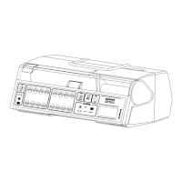
Details on connecting external equipment like nurse call or detectors.
List of conditions that trigger pump alarms.
Procedure to acknowledge and cancel active alarms.
Alarm triggered by high system pressure or occlusion.
Information on battery status, low battery warnings.
Details on connecting the pump to a nurse call system.
How to temporarily silence audible alarms.
Explanation of illuminated pictograms indicating specific alarms.
Indicators for pump running, mains, and battery operation.
Description of messages and parameters displayed in the LCD window.
General technical introduction to the pump's design and features.
Explanation of the overall electronic circuit design.
Details on microcontrollers, motor control, and signal management.
Covers IR interface, memory, display, and parameter input.
Details on power supply, voltage monitoring, and system checks.
Description of audible alarms, repeat functions, and other operational aspects.
Information about future improvements and compatibility with existing models.
Steps for visually inspecting the pump's external components.
Procedures for checking various functional aspects of the pump.
Understanding how trumpet curves relate to flow rate accuracy.
Table mapping fault codes to their meanings and causes.
Recommended actions for each specific fault code.
Steps for safely disassembling the pump's outer casing.
Procedure for removing the main printed circuit board (PCB).
Steps for removing the display printed circuit board and covers.
Procedure for removing the pump's mechanical drive assembly.
| Manufacturer | Arcomed |
|---|---|
| Model | Volumed uVP7000 |
| Power Supply | 100-240 VAC, 50/60 Hz |
| Volume to be Infused (VTBI) | 0.1 - 9999 ml |
| Accuracy | ±5% |
| Alarms | Air-in-line, Occlusion, Low battery |
| Battery Life | Typically 8 hours at 5 ml/h |
| Power Source | Rechargeable battery or AC power |
| Display | LCD |