GENERAL INFORMATION 15
* Turbo models
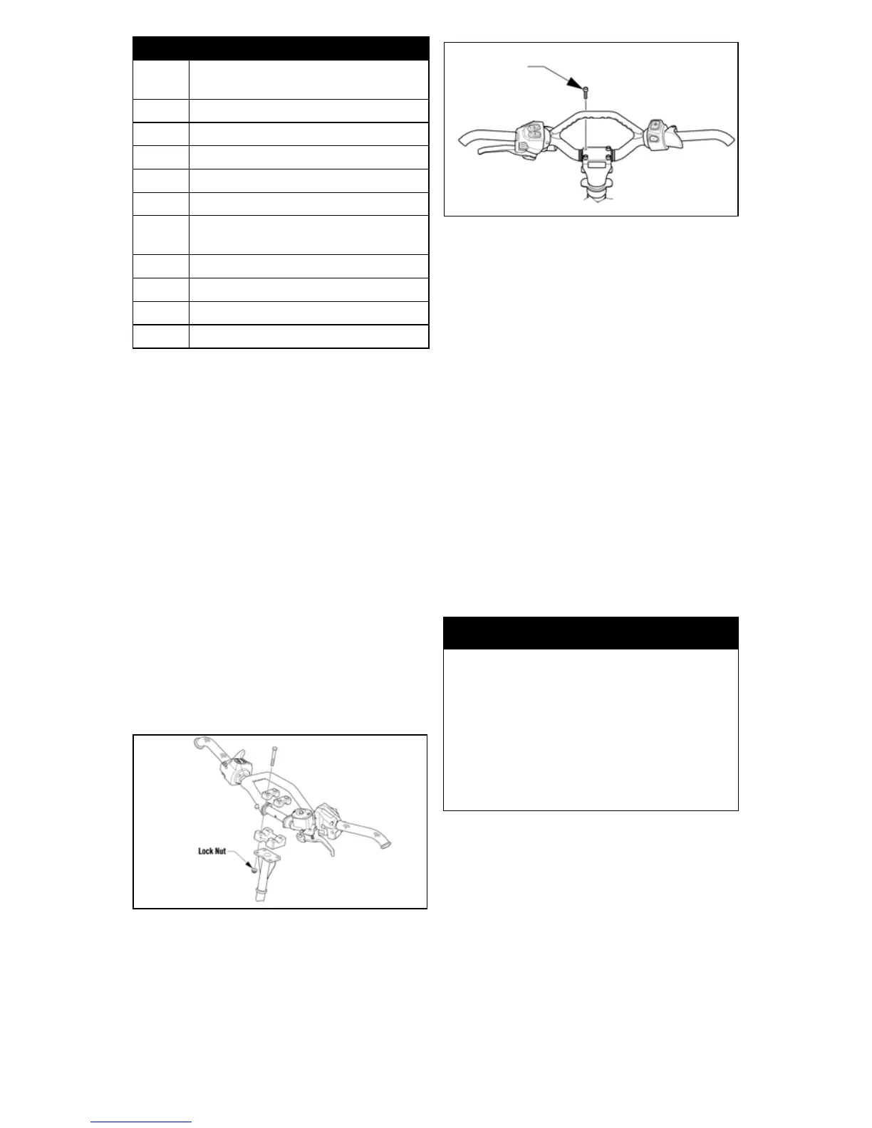
HANDLEBAR TILT
(Bearcat/Crossfire/
M-Series Models)
The handlebar can be adjusted to the
position providing the operator with
the most comfort. To adjust the handle-
bar, use the following procedure:
NOTE: It may be necessary to
remove the handlebar cover for
this procedure.
1. Loosen the four lock nuts (Allen-
head cap screws on models with a
telescoping handlebar) securing
the handlebar caps and block to
the steering post.
0743-442
0743-467
2. Adjust the handlebar up or down
to operator’s desired tilt; then
tighten the lock nuts/cap screws
evenly and securely. Check steer-
ing for maximum right/left turning
capabilities.
3. Recheck lock nuts/cap screws;
tighten securely.
NOTE: Recommended torque
value of lock nuts is 18 ft-lb. Rec-
ommended torque value for the
Allen-head cap screws is 20 ft-lb.
NOTE: Do not adjust the handle-
bar to a position that allows the
brake fluid to be below the low
mark on either side of the master
cylinder.
HANDLEBAR TILT
(F-Series/T-Series -
STD Models)
The handlebar can be adjusted to the
operator’s preference. To adjust the han-
dlebar, use the following procedure:
1. Loosen the eight cap screws secur-
ing the handlebar caps to the riser
and the riser to the steering post.
9
Failure in crankshaft position sen-
sor.
11 Failure in speed sensor.
12 Failure in coil (#1).
13 Failure in coil (#2).
14 Failure in ISC valve.
15 Failure in oxygen sensor.
19 Failure in camshaft position sen-
sor.
21 Failure in knock sensor.
22* Failure in coil (#1 secondary).
23* Failure in coil (#2 secondary).
OCTN* Low octane gasoline.
Code Trouble
! WARNING
Tighten lock nuts according to
specifications to prevent unex-
pected “movement” of the handle-
bar during operation over rough
terrain and DO NOT position han-
dlebar so steering (maximum right/
left turning capabilities) or throttle
and brake controls are affected.