7
Plenum pressure F75R F101
50 PA (0.20") 5 turns open 3 turns open
75 PA (0.30") 3 turns open 1 1/2 turns open
100 PA (0.40") 1 turn open 0 turns open
Furnace Installation
FLOOR PROTECTION
If the floor is combustible, it must be protected by 7 mm
(9/32") or thicker of noncombustible material extending 150 mm
(6") from the sides and rear, and 460 mm (18") from the front.
DUCT WORK
Minimum sizes:
F75R
Return air: 1520 sq. cm (220 sq. in)
Supply air: 1290 sq. cm (200 sq. in)
F101
Return air: 1610 sq. cm (250 sq. in)
Supply air: 1420 sq. cm (220 sq. in)
NOTE: The height of the return air inlet must not be higher
than the warm air registers. A fresh air duct must be in-
stalled into the return air system (the recommended size is 8"
diameter).
INSTALLATION AS A FORCED AIR WOOD
FURNACE
Be sure that you have the following:
• Wood furnace module # F75R or F101
• Blower - Delhi model 210 or Lau DUA10
• Motor - 1/3 HP, 1800 RPM, 110 V 60 Hz
• Connecting duct model FCADB
• Control kit model FCFC1, which includes:
• Thermostat
• Damper motor
• Fan/limit control
• Transformer c/w wiring harness
NOTE: OBSERVE MINIMUM CLEARANCES! If you need to
reduce the rear clearance, you can cut it to half (50%) if you
protect combustible surfaces with .3mm (.013") or heavier
sheet metal. You must space the sheet metal out 25 mm (1")
by non-combustible spacers (see CSA Installation code
B366 - 1791).
ASSEMBLY
After deciding which side is best for the blower unit,
remove the inlet cover on that side. Use the screws to attach
the connector. The blower sits on top of the connector,
oriented so that the air moves down into the wood furnace
when the blower is on. Make sure that the fan pulley is 203
mm (8") in diameter.
After measuring the pressure in the hot air plenum, set the
motor pulley as follows:
ELECTRICAL COMPONENTS
1. Install the damper motor using the holes provided
beside the control chain.
2. Install the fan/limit control bracket using the holes
provided on the centre of the front of the furnace. The fan/
limit control can be installed after the hot air plenum is in
place.
3. Install the junction box with the transformer on the top
front corner of the furnace nearest to the blower.
4. Install the room thermostat on a wall centrally located in
the home. It should be located away from the direct heat of
the furnace or a hot air duct.
5. Connect the wiring as shown inFigure 6.
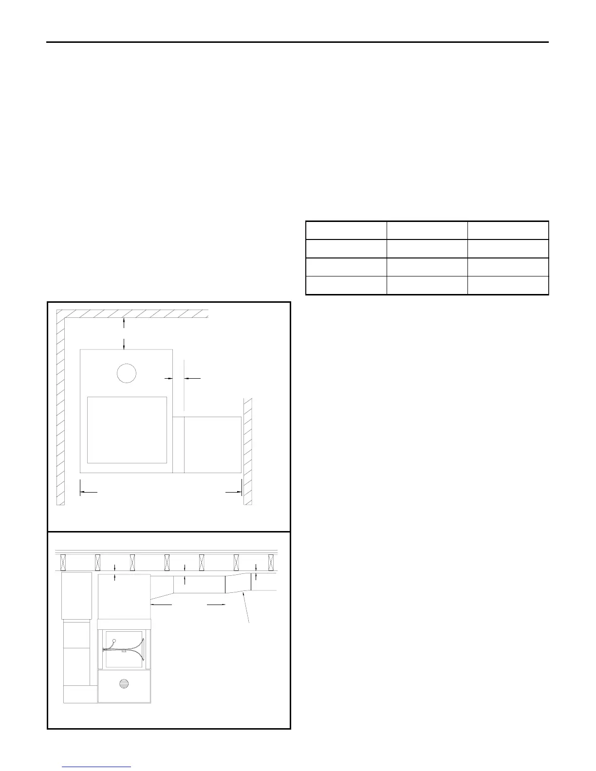
*** Be sure to provide access
for cleaning the flue pipe ***
370 mm (14 1/2")
125 mm (5")
150 mm (6")
25 mm (1")
furnace
blower
Figure 5a: Clearances
2m (6')
50 mm (2")
50 mm (2"0)
25 mm (1")
supply duct
furnace
connecting
duct
blower
return air
plenum
Note: If the supply air duct is routed
below furnace level (e.g., in the crawl
space underneath) then the power failure
mode must be deactivated (see page 4).
Figure 5b: Duct clearances