9
Furnace Installation
NOTE: The installation must comply with CAS Standard
B365-M87 - "Installation Code For Solid Fuel Burning
Appliances And Equipment."
If any changes are required on the oil furnace, these must
comply with CSA Standard B139 "Installation Code for Oil
Burning Equipment."
Prepare the plenums and connecting ducts:
• The connecting duct between the oil furnace and the
wood furnace must be 305 mm x 460 mm (12" x 18") with
elbows having a minimum inside radius of 150 mm (6").
• Do not connect duct work so that reverse flow is
possible (the cold air return must not be higher than the
warm air outlets).
• After the installation is complete, recheck the air flow as
before. If the air flow is less than before, the blower speed
must be increased to compensate for the pressure drop
through the system.
• For multi-speed blower motors, use the higher speed, if
needed.
• For belt-driven blowers, adjust the pulley diameter on the
motor to give the extra speed required. If necessary, a
larger blower motor may be used if the faster speed
increases the air flow above the rating on the motor
nameplate. HOWEVER, THE BLOWER MUST NOT BE
CHANGED.
• Follow the wiring diagram precisely.
INSTALLATION AS AN ADD-ON TO AN
ELECTRIC FURNACE
Be sure that you have the following:
• Wood furnace module # F75R or F101
• Control kit model FEFC3, which includes:
• Thermostat
• Damper motor
• 2 fan/limit controls mounted on a bracket
• Wiring harness with LV terminal block
Your electric furnace blower must be large enough to keep
the furnace equal to or below the following maximum tempera-
ture rises:
WARNING: If the airflow is too low, your installation will be
unsafe.
NOTE: The temperature rise must be measured between the
inlet and the outlet of the electric furnace only.
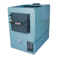
If the electric furnace is certified for counter-flow opera-
tion (upside down) it should be installed according to Figure
5b. Use the connecting duct (part FCADB) in the installation.
Its dimensions are shown in Figure 9.
Furnace Size
Output
(BTU/hr)
Max temp. rise,
F75R °C (°F)
Max temp. rise,
F101 °C (°F)
10 kW 34100 24° (43°) 21° (37°)
15kW 51200 36° (65°) 31° (65°)
20 kW 68200 42° (75°) 41° (73°)
25 kW 85300 42° (75°) 42° (75°)
30 kW 102400 N/A 42° (75°)
35 kW 119400 N/A 42° (75°)
Figure 9: Connecting duct (part # FJADB)
165 mm
(6 1/2")
432 mm (17")
432 mm (17")
305 mm
(12")
460 mm
(18")
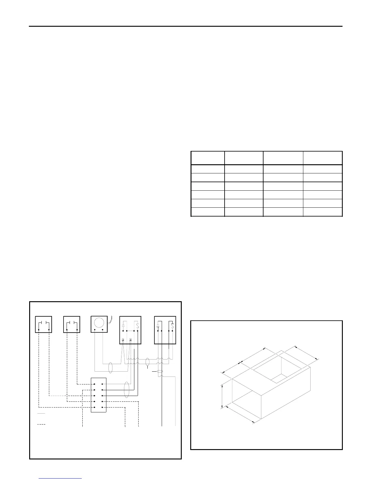
blower (not used)
aux. limit
140° F
damper
motor
wood
thermostat
oil or gas
thermostat
wire supplied by
customer
wire supplied with
harness
*
*
jumper
removed
to
blower
motor
110 V
source
24 V
source
common
from 24 V
transformer
low voltage
terminal block
black
white
green
16/3
LVT
16 /2
LVT
14 /2
BX
limit
blower
limit
Figure 8: Wiring diagram for adding on to oil or gas (control kit #FEFC2)
blower and wood
limit - 250°F
to furnace
start relay