EasyManua.ls Logo

Arduino UNO R4 WiFi User Manual

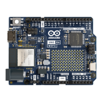
Arduino UNO R4 WiFi
23 pages
To Next Page IconTo Next Page
To Previous Page IconTo Previous Page
Page #2 background image
Arduino® UNO R4 WiFi
2 / 23 Arduino® UNO R4 WiFi Modified: 26/06/2023
Features
The R7FA4M1AB3CFM#AA0, often referred to as RA4M1 in this datasheet, is the main MCU on the UNO R4 WiFi,
connected to all pin headers on the board as well as all communication buses.
Overview
48 MHz Arm® Cortex®-M4 microprocessor with a floating point unit (FPU)
5 V operating voltage
Real-time Clock (RTC)
Memory Protection Unit (MPU)
Digital-to-analog Converter (DAC)
Memory
256 kB Flash Memory
32 kB SRAM
8 kB Data Memory (EEPROM)
Peripherals
Capacitive Touch Sensing Unit (CTSU)
USB 2.0 Full-Speed Module (USBFS)
14-bit ADC
Up to 12-bit DAC
Operational Amplifier (OPAMP)
Power
Operating voltage for RA4M1 is 5 V
Recommended input voltage (VIN) is 6-24 V
Barrel jack connected to VIN pin (6-24 V)
Power via USB-C® at 5 V
Communication
1x UART (pin D0, D1)
1x SPI (pin D10-D13, ICSP header)
1x I2C (pin A4, A5, SDA, SCL)
1x CAN (pin D4, D5, external transceiver is required)
See the full datasheet for the R7FA4M1AB3CFM#AA0 in the link below:
R7FA4M1AB3CFM#AA0 datasheet
The ESP32-S3-MINI-1-N8 is the secondary MCU with a built-in antenna for Wi-Fi® & Bluetooth® connectivity. This
module operates on 3.3 V and communicates with the RA4M1 using a logic level translator (TXB0108DQSR).
Overview
Xtensa® dual-core 32-bit LX7 microprocessor
3.3 V operating voltage
40 MHz crystal oscillator
Question and Answer IconNeed help?

Do you have a question about the Arduino UNO R4 WiFi and is the answer not in the manual?

Arduino UNO R4 WiFi Specifications

General IconGeneral
Operating Voltage5V
Input Voltage6-24V
Digital I/O Pins14
PWM Pins6
Analog Input Pins6
Flash Memory256 KB
SRAM32 KB
EEPROM8 KB
Clock Speed48 MHz
Wi-FiYes
BluetoothYes
USB ConnectorUSB-C
Dimensions68.6 mm x 53.4 mm
DC Current per I/O Pin8 mA
UARTYes
SPIYes
I2CYes
CANNo
MicrocontrollerRA4M1 (Arm Cortex-M4)

Summary

Description

Target Areas

Identifies intended users and applications, including makers, beginners, and educational purposes.

Features

Microcontroller (RA4M1) Specifications

Details the RA4M1 MCU, its clock speed, operating voltage, memory, and key peripherals like DAC and MPU.

Wi-Fi & Bluetooth Module (ESP32-S3)

Describes the ESP32-S3 module, its dual-core processor, Wi-Fi/Bluetooth capabilities, and operating voltage.

Power and Communication Interfaces

Covers operating voltage, input voltage, USB-C power, and communication interfaces like UART, SPI, I2C, CAN.

The Board Overview

Application Examples and LED Matrix

Highlights entry-level projects, IoT applications, and the programmable LED matrix feature for projects.

Related Arduino Products

Lists other Arduino UNO series products such as UNO R3, UNO R3 SMD, and UNO R4 Minima.

Recommended Operating Conditions

Block Diagram

Board Topology

Front View Component Identification

Details the components and connectors visible on the front of the Arduino UNO R4 WiFi board.

Microcontroller (R7FA4M1AB3CFM#AA0)

Wi-Fi / Bluetooth Module (ESP32-S3-MINI-1-N8)

ESP Header Details

USB Bridge Functionality

USB Connector

LED Matrix Functionality

Digital Analog Converter (DAC)

I2C Connector Details

Power Options

Power Tree Overview

Illustrates the power distribution from input sources (VIN, USB-C) through regulators to board components.

Pin Voltage Specifications

Details the operating voltages for the UNO R4 WiFi (5V) and ESP32-S3 module (3.3V).

Pin Current Handling

Specifies the safe current handling capacity of the RA4M1 microcontroller GPIOs (8mA).

Pinout Reference

Analog Pins

Lists analog pins, their functions (input, DAC, OPAMP), and associated MCU pins.

Digital Pins

Details digital pins, their functions (GPIO, PWM, I2C, SPI, UART, CAN) and associated MCU pins.

OFF and ICSP Pin Definitions

Details the function of the OFF pin for power control and the ICSP header for programming/debugging.

Mounting Holes and Board Outline

Board Operation and Getting Started

Getting Started with Arduino IDE

Instructions for setting up and using the Arduino Desktop IDE for programming the board.

Getting Started with Arduino Web Editor

Guidance on using the online Arduino Web Editor for coding and uploading sketches to the board.

Arduino IoT Cloud Integration

Information on leveraging Arduino IoT Cloud for monitoring, logging, and automating IoT projects.

Board Recovery Procedure

Steps for recovering the board if a sketch causes it to become unresponsive via USB.

Declaration of Conformity (CE)

RoHS & REACH Compliance

Conflict Minerals Declaration

FCC Caution and RF Exposure

Company Information

Reference Documentation Links

Change Log

Related product manuals