DXC5K/EN IN/A22 Installation
Page 14/34
DXC 5000
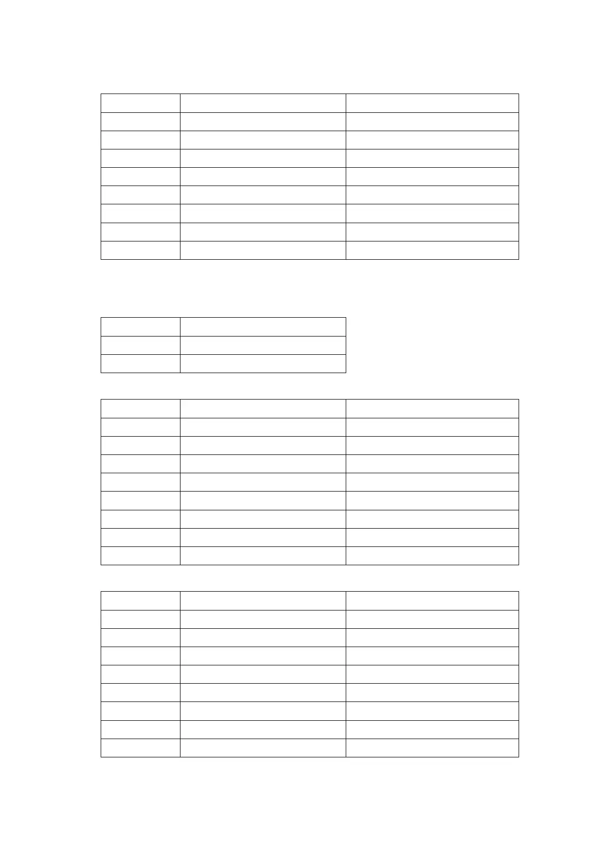
The two RJ45 jacks are wired as follows:
Pin Number Signal Signal Direction
1 Transmit Data + Output from DXC 5000
2 Transmit Data - Output from DXC 5000
3 Receive Data + Input to DXC 5000
4 No Connection
5 No Connection
6 Receive Data - Input to DXC 5000
7 No Connection
8 No Connection
TABLE 7: RJ-45 FOR 10M AND 10/100M PIN ASSIGNMENT
For each of the U-interface ports, U-PORTs, connection to the line is by RJ48C connector.
The pin definition is listed in Table 2-9.
Pin Number Signal
4 TIP
5 RING
TABLE 8: U- PORT U-INTERFACE RJ48C TERMINALS
Pin Number Signal Signal Description
1 Unassigned
2 Unassigned
3 Unassigned
4 Loop 1 Tip Tip
5 Loop1 Ring Ring
6 Unassigned
7 Chassis Ground/ Unassigned
8 Chassis Ground/ Unassigned
TABLE 9: LINE HDSL CONNECTOR
Pin Number Signal Signal Description
1 Pair 1-A
2 Pair 1-B
3 Pair 2-A
4 Pair 2-B
5 Pair 3-A
6 Pair 3-B
7 Pair 4-A
8 Pair 4-B
TABLE 10: RJ45 PIN ASSIGNMENT - N1 & N2 OF DRY CONTACT I/O CARD