EasyManua.ls Logo

Arico V100 User Manual

Arico V100
4 pages
To Next Page IconTo Next Page
Page #1 background imageLoading...
Page #1 background image
V Series Temperature Controllers
User's manual
(21)Specifications
1 100240VAC±10, 50/60HZ
2. 2 * 4
3. 4
4. 0.5% 25)
5. TC: JK       RTD: Pt100
6. :    
  250V NO:7A / NC:5A      
  Digital. DC24V/20mA
  010V05V15V
  020mA420mA
Alarm1/2 & Aux.outputl
Relay250V NO:7A / NC:5A
Digital VoltageDC24V/20mA
(* V Series output for aux. and alarm1/2 : 250V/5A)
7.
8. ON/OFF, PID
9.
10. 055(32℉~130)
      10%80%
. Power Supply
Display digits
Key machinery keys
Accuracy full scale (
Main Input
OutputMain output
Relay
Voltage
Analog volt.
Analog current
FunctionHeating and cooling
Control Mode
Alarm Mode10
AmbientTemperature
Humidity (non-condensing)
(22)Wiring
Thank you for purchasing model V Series PID
Temperature Controller.
Before installing, connecting or using the instrument,
please go through this instruction manual
carefully and use the unit in proper manner.
VNA0000006
ARICO Technology Co., Ltd. reserves the right to
make any kind of design or functional modification
at any moment without prior notice.
Website:www.arico.com.tw E-mail:infoarico.com.tw
Ver.:1.0.9
V100 V300
V200V500
V400
Question and Answer IconNeed help?

Do you have a question about the Arico V100 and is the answer not in the manual?

Arico V100 Specifications

General IconGeneral
Operating Temperature0-50°C
Input TypeThermocouple, RTD
OutputRelay, SSR
DisplayLED
Resolution0.1°C
Control ModePID

Summary

Specifications and Wiring Diagrams

General Specifications

Details power supply, display, accuracy, input types, output types, control modes, and ambient conditions.

V100, V300, V200, V500, V400 Wiring

Wiring diagrams illustrating connections for various V Series models.

Faceplate and Key Operation

Faceplate Overview

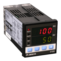
Explanation of display indicators like PV, SV, OUT1, OUT2, AL1, and AL2.

Key Operation Guide

Instructions for using Level, Set, Increment, and Decrement keys for navigation and control.

PID Control and Tuning

Control Modes and Parameters

Details output control modes, heating/cooling modes, and PID tuning parameters (P, I, D).

PID Control and Self-Tuning

Explains PID control principles and the PID Value Self Tuning feature.

Other Functions and Features

Dimension and Alarm Settings

Physical dimensions for models and configuration of alarm range and hysteresis.

Control Types and Output Functions

Details ON/OFF control, manual control, and types of output functions (Relay, Digital, Analog).

Parameter Management

Covers password protection, thermocouple types, unit selection, offset, and default restore.

Error Messages and Special Functions

Lists error messages like Thermocouple breaking and special functions like Manual Output Control.

Order Code Guide

Guidance for selecting model, outputs, and alarms when ordering the instrument.

Parameter Configuration Flow Chart

Level 1 Parameter Details

Description of parameters accessible in Level 1, including output settings and alarm ranges.

Level 2 Parameter Details

Description of parameters in Level 2, covering control modes, cycle times, and hysteresis bands.

Level 3 Parameter Details

Description of Level 3 parameters, including manual output, alarm modes, and analog output limits.

Level 4 Parameter Details

Description of Level 4 parameters, including password, units, temperature offset, and default restore.

Related product manuals