GB - 8
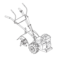
Install Reverse Clutch Cable
1. Locate the reverse clutch cable installed on the
left side of the sheave housing.
2. Remove the nut from the cable end and install the
cable into the inside hole of the mounting bracket
on the handlebar.
3. Replace the nut onto the cable end. Do not
tighten until cable adjustments have been made.
4. Install the rubber cap.
5. Install the cable eye to the reverse lever.
6. Adjust cable. See
Service and Adjustments.
7. Install a tie strap to secure the both clutch cables
to the handlebar. Use tie strap below mounting
bracket.
Check Tire Pressure
Check tire pressure using a low pressure tire gauge for
accurate reading. For correct pressures, refer to
Specifications
.
Check Engine Oil
Engine is shipped without oil in the engine crankcase.
Fill oil to proper level. Refer to engine manual for
detailed instructions.
Fill Fuel Tank
Refer to engine manual for proper type. Fuel tank
capacity is 3 qts. (2.84L).
Check Lubrication
Check for proper lubrication. Refer to
Maintenance
.
Check Function of all Controls
Ensure unit runs and performs properly. Refer to
Operation
.
Test Operator Presence System
1. Start engine in a flat, open area.
2. Engage forward clutch control.
3. Ensure unit drives forward and tines rotate
forward.
4. Release forward clutch control and ensure wheel
drive and tines come to a complete stop.
5. Engage reverse clutch control.
6. Ensure unit drives backward and tines rotate
backward.
7. Release reverse clutch control and ensure wheel
drive and tines come to a complete stop.
IMPORTANT:
DO NOT operate unit if operator
presence system does not function properly. See
Service and Adjustments
to adjust clutches or see your
dealer.
1. Cable Eye
2. Bolt
3. Rubber Cap
4. Nut
5. Forward Clutch
Cable
6. Flanged Bushing
7. Locknut
8. Mounting Bracket
1
2
3
Figure 6
4
5
6
7
8
1. Cable Eye
2. Rubber Cap
3. Nut
4. Reverse Clutch Cable
5. Mounting Bracket
6. Tie Strap
Figure 7
1
2
3
4
5
6
WARNING:
FAILURE OF CONTROLS could
result in death or serious injury.
CAUTION:
DO NOT attempt to start your
engine at this time. Thoroughly read this
manual and engine manual.