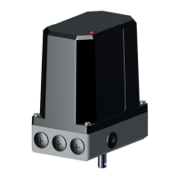
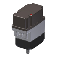
The ARIS actuator, specifically the Tensor² series (including Tensor² Highspeed, Tensor²+ (Option), and Tensor²+ Zone 2/22 (Option)), is an electrical actuator designed for industrial use. This manual serves as the original declaration of incorporation and provides detailed instructions for its installation, operation, and maintenance.
Function Description
ARIS actuators are designed to operate regulating and shut-off appliances such as valves, ball valves, taps, slide valves, and dosing pumps. They are partly completed machinery conforming to directive 2006/42/EC, with further compliance to EMC Directive 2014/30/EC and LVD Directive 2014/35/EC. For use in potentially explosive atmospheres of Zone 2 and 22, the Tensor²+ models meet the requirements of the ATEX directive 2014/34/EC, specifically for device group II, category 3 D (ignition protection type "Protection by enclosures") and group II, category 3G (ignition protection type "Increased safety").
The actuator's core function involves precise control of movement, allowing for left-turning (CCW) and right-turning (CW) operations. This control can be achieved via external signals (current, voltage, or potentiometer) or through onboard buttons in manual mode. Position feedback is provided digitally via a magnet sensor, and optionally through an electrical potentiometer or current/voltage output. The device incorporates stall detection to prevent damage from blockages and block detection near end positions to suppress stall errors in these ranges.
Important Technical Specifications
General:
- Voltage Supply: 85-265 V AC (50/60 Hz) / 19.2-28.8 V DC
- Motor: BLDC-Motor
- Protection Class: IP65 (IP 66/IP 67 Option)
- Ambient Temperature: -15 °C to +60 °C (other temperature ranges optional). For Zone 2/22 models, the range is -15 °C to +50 °C, with a maximum surface temperature of +80 °C.
- Installation Position: Arbitrary
- Travel: >28° to 100 revolutions
- Display: OLED-Display 0.96"
Connection:
- Tensor²: 3 cable entries M16x1.5 (provided by customer)
- Tensor² HS: 3 cable entries M20x1.5 (provided by customer)
- Zone 2/22 Models: Only ATEX-certified cable entries with O-ring seals are allowed. Examples include WISKA Hoppmann & Muslow GmbH, Type ESKE/1-e 16.
Control and Feedback:
- Position Feedback: Digital via magnet sensor.
- Potentiometer (Option): Electronical.
- Resolution: 12 bit
- Output Impedance: 1 kΩ
- Supply Voltage: 4.75-28.8 V DC
- Set Value Input (i-Act controller):
- Current Input: 0-20 mA, Burden 50 Ω
- Voltage Input: 0-10 V DC, Input impedance >200 kΩ
- Actual Value Output (i-Act controller):
- Current Output: 0-20 mA, Burden 50 Ω
- Voltage Output: 0-10 V DC
- Relay Switch (Option board):
- Amount of Relays: 2 (optional 4)
- Relay Type: Bi-stable relay
- Switching Voltage: max. 250 V AC / 125 V DC
- Allowed Continuous Current/Channel: max. 2 A (at 230 V AC / 30 V DC); max. 0.2 A (at 125 V DC)
- Message Output: Potential-free contact (terminals 56|57).
- Switching Voltage: 250 V AC / 30 V DC
- Allowed Continuous Current: 3 A
Usage Features
The actuator is operated via three onboard buttons (LEFT, MENU, RIGHT) and a slide switch (AUTO/MANU), with an OLED display facilitating setup and monitoring.
Operating Modes:
- Automatic Operation (AUTO mode): The actuator responds to external signals (terminal clamps, signal clamps, or CAN clamps). Onboard buttons are inactive.
- Manual Mode (MANU mode): The actuator can be driven left or right using the L & R buttons, provided it is not in setup mode.
- Setup Mode: Accessed from MANU mode by pressing the MENU button for >1s. Allows adjustment of various parameters. Navigation is done with L & R buttons, confirmation with a short MENU press, and exit with a long MENU press or by switching to AUTO mode.
Key Settings and Adjustments:
- End Positions: Left and right end positions can be set and stored. A minimum difference of 28° is required between end positions.
- Poti Input/Output: Configuration for external potentiometer control and position feedback.
- Set Value/Actual Value: Settings for input and output signals when using i-Act controller. Defaults for end positions must cover a minimum of 20% of the total range.
- Relay Switch: Configuration of bi-stable relays for position feedback or block detection.
- Wire Monitor: Monitors the set value signal for cable breakages, triggering an error code (90) if the signal falls below a threshold. The actuator's behavior upon detection (stop, move to open/close, or move to preset position) can be configured.
- Offset (Control Variance): Defines the maximum allowed variance between actual and set values in controller mode, indicating an error if exceeded.
- Hysteresis (Shut-off and Turn-on): Defines the accuracy and readjustment points for the actuator. Shut-off hysteresis must be lower than turn-on hysteresis.
- Stall Detection: Recognizes accidental halts and stops the actuator to prevent damage, displaying an error code (3X).
- Block Detection: Detects intentional blocks near end positions within a settable range (1-10%), suppressing stall errors.
- Acceleration/Brake Ramp: Defines the time (in ms) for acceleration and braking in AUTO mode.
- Add Feature: Allows activation of additional features (e.g., potentiometer, current/voltage output, i-Act functionality) via an access code.
Maintenance Features
ARIS actuators of the Tensor² series are designed for minimal maintenance.
- Lubrication: They feature lifetime lubrication.
- Operating Hours Counter: Displays the total operating hours, which starts when power is supplied and is stored even after power failure. This counter cannot be reset.
- Modules Information: Displays connected add-on boards, marking recognized boards with an asterisk. Add-on boards must only be mounted/dismounted when the electronics are de-energized.
- Parameter RESET: A function to restore factory settings. This involves a specific sequence of actions in a de-energized state, holding L&R buttons, and then powering on. After reset, end positions must be set anew, and all settings checked.
- Troubleshooting: The manual provides a list of error codes and corresponding troubleshooting steps. For issues that cannot be resolved, contacting ARIS customer service is recommended.
- Spare Parts: Spare parts can be ordered by contacting aris@stellantriebe.de, providing the actuator's serial number.