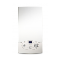
Do you have a question about the Ariston ALTEAS ONE and is the answer not in the manual?
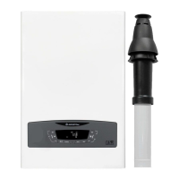
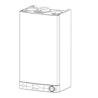
Physical dimensions and layout of the boiler unit, including connection points.
Internal components of the combi boiler model with labeled parts.
Internal components of the system boiler model with labeled parts.
Diagram illustrating the boiler's water flow, components, and connections.
Location of important labels on the boiler unit for identification.
Explanation of the boiler's user interface, buttons, and their functions.
Overview of the boiler's display icons, messages, and information shown.
Functionality and features of the CUBE wired room sensor.
Step-by-step guide for initial boiler setup, calibration, and configuration.
How the boiler functions during heating operation, including component sequences.
How the boiler operates when providing domestic hot water, including component sequences.
Boiler operation in tank mode for hot water storage management.
Boiler operation in system mode for heating and hot water.
Function to prevent Legionella bacteria growth in stored water.
Diagram showing hydraulic connections for system versions.
Function for boiler combustion analysis and gas calibration.
Function to reduce hot sanitary water output time by keeping the primary circuit hot.
Protection function against freezing of the boiler's water circuits.
Checks related to water flow and potential safety shutdowns.
Procedure to remove air from the primary heating circuit after filling.
Setting for automatic heating restart delay based on temperature.
Description and function of the 3-way diverter valve and its motor.
Function and antiscale limit temperature for the secondary heat exchanger.
Details on the boiler's circulation pump models and operation.
Different post-circulation modes and their conditions.
Function and error codes related to the heating pressure sensor.
Procedure for filling the heating circuit using the tap.
Procedure for emptying the heating system using the drain valve.
Description and function of the boiler's condensation trap.
Explanation of the automatic by-pass function for exchanger protection.
Details on the XTRATECH primary heat exchanger and coil configuration.
Location and maintenance of the heating return filter.
Technical specifications and function of the expansion vessel.
Function of the DHW flow meter and its settings.
Use of flow limiters for high sanitary flow rates.
Description of temperature sensors (NTC1, NTC2) and error codes.
Overview of the main components of the burner unit.
Details on the premix burner pot and its construction.
Information about the mixer and gas diaphragm.
Procedure for changing the boiler's gas type using auto adaptation.
Different silencer types and their air inlet diameters.
Description of the Bertelli SGV gas valve and its operators.
How the boiler manages combustion and gas settings automatically.
Procedure to check the inlet gas pressure against gas type.
Adjusting CO2 levels for DHW at maximum power.
Adjusting CO2 levels for intermediate power settings.
Adjusting CO2 levels for minimum power settings.
Table of gas-related parameters and settings.
Components for analyzing flue gas composition (O2, CO2).
Function of ignition and flame detection electrodes.
Location of the spark generator on the main PCB.
Function and types of the modulating speed fan.
Options for connecting flue gas exhaust systems.
Description of the GAL2EVO COND electronic main card.
Wiring diagram for the boiler's electronic system and connections.
How to connect external devices like thermostats and sensors.
Installation of decoupling clip-in for solar/hybrid modules.
Steps to connect the boiler to a Wi-Fi network.
Activating remote control services via App or Web App.
Overview of error codes, remote management, and troubleshooting steps.
Accessing and navigating the user-level settings menu.
Accessing and navigating the technician-level settings menu.
Overview of menu sections including Network, Boiler, Zone, and Service parameters.
Overview of boiler malfunction types, error handling, and shutdown classifications.
Detailed list and descriptions of boiler error codes by functional unit.
| ErP Rating | A |
|---|---|
| Modulation | 1:10 |
| Heating Output | 24 kW to 35 kW |
| DHW Output | 24 kW to 35 kW |
| Fuel Type | Natural gas or LPG |
