14 / EN
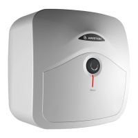
INSTALLATION INSTRUCTIONS
a) For the user
In order to obtain the best performance from the heater, the sacrificial anode must be checked every
year and replaced as necessary. If the heating element is heavily coated with scale we recommend
descaling and removing any lime deposit from the heater at the time of this inspection. Where the ad-
ditional cold water controls are fitted, the expansion vessel will need to be recharged by the installer.
Important note: The heater must be serviced annually. Failure to service which includes inspection
and replacement of the sacrificial anode will invalidate warranty.
b) For the installer
WARNING: Switch o the power first.
Access to the electrical components, the magnesium anode and water container is gained by un
-
screwing the 2 screws on the front cover.
If the thermal cut-out has operated the cause must be found before resetting.
To drain the heater close the service valve and:
i) for under-sink models disconnect pipes and removed the heater from the wall.
ii) for over-sink models undo the cold water supply pipe and open a hot water tap.
The heating element may be removed (after taking out the thermostat phials on model 30 L) by un-
doing the M6 nut.
The assembly should then be turned through 90° anti-clockwise to ease removal from the water
container. Once the element is free from the water container the anode may then be inspected and
removed if necessary
When reassembling the cover make sure that the regulation knob is coupled with the thermostat.
Check controls (where fitted) as per the following:
- Line strainer - with the water supply turned o remove screen from strainer and clean of any detritus;
- Expansion vessel - with the water supply turned o and taps open, check expansion vessel pres-
sure and top up as necessary;
- Temperature & pressure relief valve - with the water supply turned on, check manually by lifting the
test lever/ turning the test knob (ensure valve closes after testing);
- Expansion relief valve - check manually by turning the test knob (ensure valve closes after testing);
- Discharge pipes (D1) - from both temperature & pressure relief and expansion relief valve for ob-
structions;
- Tundish & discharge pipe (D2)- open either valve gradually to produce a full bore discharge into
tundish and D2 without any back pressure;
- Pressure reducing valve - check that the correct outlet pressure is being maintained by recording
the pressure at an in-line terminal fitting i.e. tap

 Loading...