instalación
installation
26
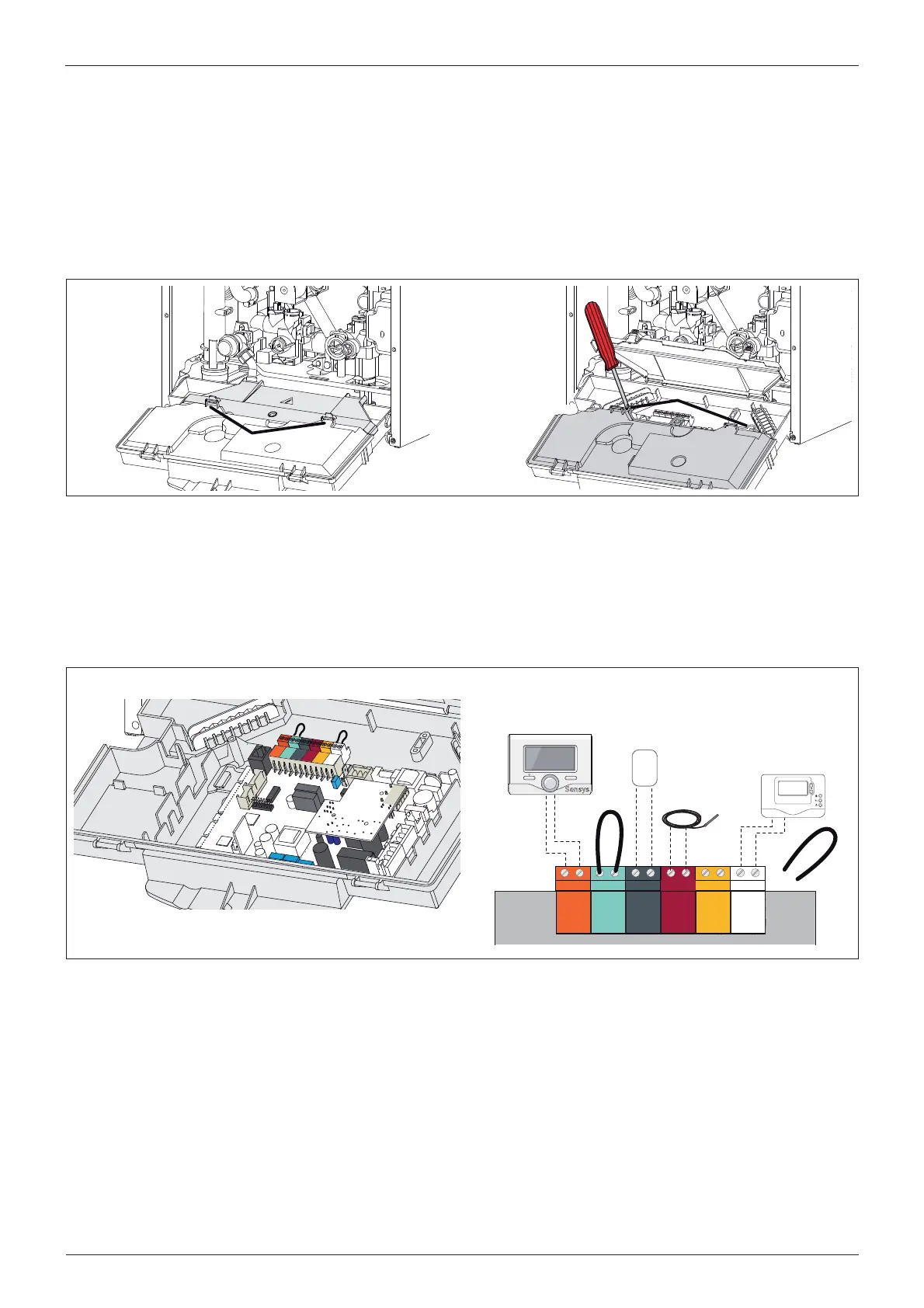
Conexión de Unidades Periféricas
Para acceder a las conexiones de los periféricos, proceda de la
siguiente manera:
- desconecte la caldera de la alimentación eléctrica
- extraiga la envoltura
- gire la caja eléctrica hacia delante
- desenganchar los dos clip “a”, girar hacia arriba el panel “b” para
acceder a la conexión de las periféricas
- desenroscar los dos tornillos “c” y quitar la tapa “d” del porta-
instrumento para acceder a la tarjeta electrónica.
Encontramos las conexiones para:
BUS = Conexión dispositivo modulante
TA2/FLOOR = termostato para suelo radiante o el termostato
ambiental 2 (seleccionado con el parámetro 223)
SE = Sonda externa
TNK = Termostato reserva sanitaria
SOL = Sonda solar
TA1 = Termostato ambiental 1
a
b
c
d
BUS
TB
FLOOR
TA2
SE TNK SOL TA1
CN1
OK
Sensys
1234567
Control Remoto
Remote Control
Sonda externa
External Sensor
Termostato Ambient
Room Thermostat 1
Termostato acumulador
Tank Thermostat
BUS
T
B
TA2
SE
TNK
SOL
TA1
Peripheral connections:
BUS = Remote control connection (modulating device)
FLOOR/ TA2 = the under oor heating thermostat or the room
thermostat 2 (selected via parameter 223 - factory setting =
under oor heating thermostat)
SE = Outdoor sensor - OPTION
TNK = Tank temperature probe
SOL = Solar temperature probe
TA1 = Room thermostat 1
Peripheral unit connection
To access peripheral unit connections carry out the following steps:
- Disconnect the boiler from the power supply
- Remove the casing by unhooking it from the instrument panel
- Rotate the control panel while pulling it forwards
- Unhook the two clips “a”, rotate the cover “b” to have access to
the peripherical connections
- Unscrew the two screws “c” and remove the cover “d” of the
instrument panel to have access to the main P.C.B.
 Loading...