Ø 80 mm
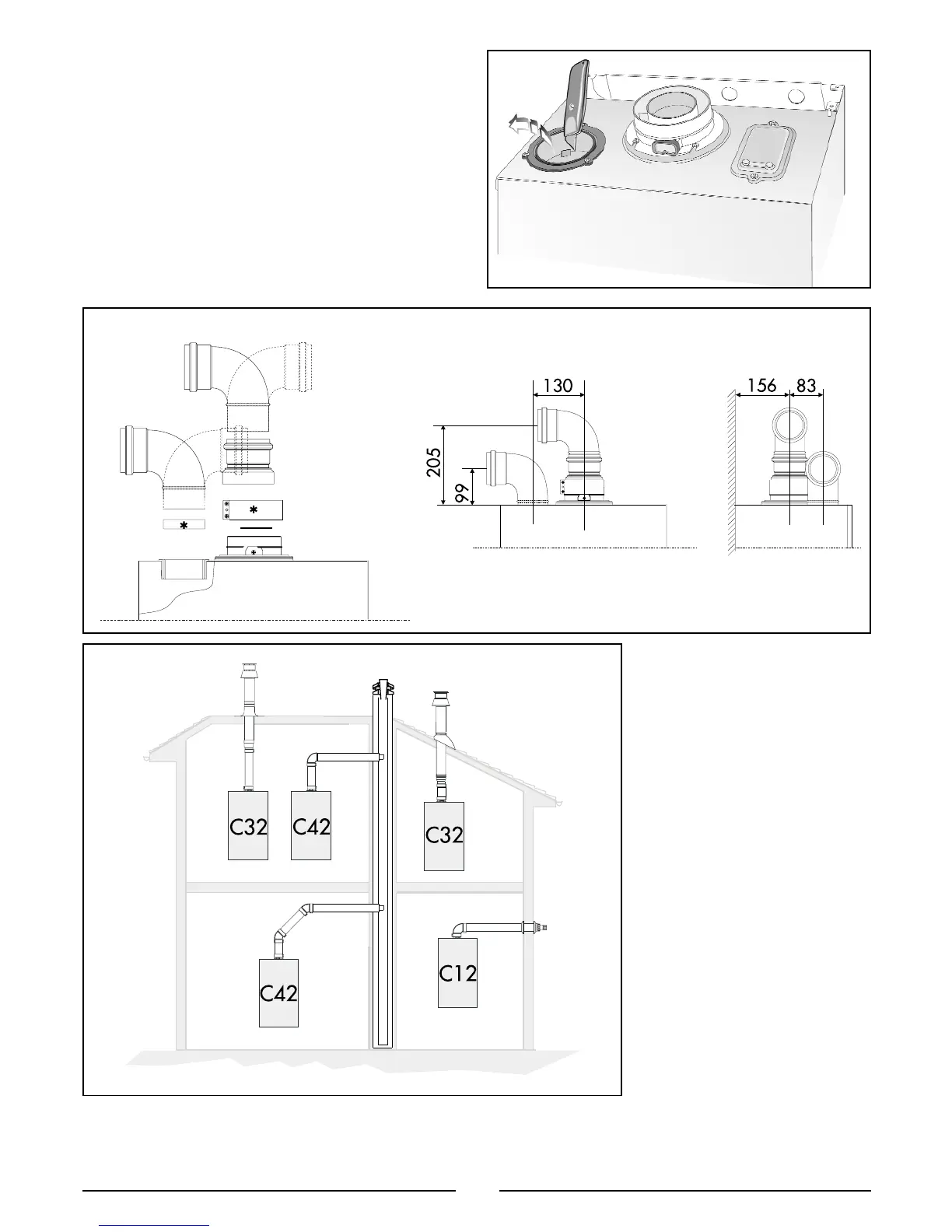
The components marked * in FIG 2.9 are present or absent
depending on the type of flue system used by the installer.
In addition, it is also possible to use a split (twin pipe)
system by fitting a special adaptor to the flue connector
and using the aperture for the air vent intake located on
the top part of the combustion chamber.
To utilise the air intake it is necessary to:
1. Remove the bottom of the air intake by cutting it with a
suitable knife (see
FIG.2.8);
2. Insert the elbow into the air intake until it reaches the
lower end. (There is no need to use gaskets or sealing
compounds).
10
IMPORTANT!
For all flue systems, a restrictor
may be be inserted into the
boilers flue connector; the
restrictor must be Ø 43 in
diameter depending on the length
of piping indicated in T
ABLE 2.1.
FIG 2.10 and FIG 2.11 illustrate
some of the various designs for
coaxial or twin pipe flue systems.
For further information on
discharge/ventilation accessories,
see the
FLUE PIPE ACCESSORIES
MANUAL.
COAXIAL SYSTEMS
FIG. 2.8
F
IG. 2.9
F
IG. 2.10
FU005A
FU006A
FU004A
FU001A

 Loading...