Supplied By www.heating spares.co Tel. 0161 620 6677
SCHEMATIC
ROOM-SEALED FAN FLUE
23 MFFI - 27 MFFI
TECHNICAL DATA
Category II 2H 3+ II 2H 3+
Type
C12, C32, C42, C52 C12, C32, C42, C52
POWER
Heat input max. kW - Btu/h 25.6 - 87,300 27.3 - 93,100
Heat i
nput min. kW - Btu/h 11.0 - 37,500 11.0 - 37,500
Heat output max. kW - Btu/h 23.7 - 80,900 27.0 - 92,100
Heat output min. kW - Btu/h 9.6 - 32,800 9.3 - 31,700
EFFICIENCY
SEDBUK Rating Band D D
CHARACTERISTICS
Heat loss to the casing (
∆
T= 50°C) % 1 1.3
Heat loss through the flue when burner on % 6.5 6.7
Heat loss through the flue when burner off % 0.4 0.4
Exhaust discharge maximum (natural gas) kg/h 51 58
Residual discharge head mbar 0.96 1.41
Consumption at nominal capacity G20
(1)
m
3
/h 2.72 3.10
Gas consumption after 10 minutes* m
3
0.32 0.36
(15°C, 1013 mbar) G30-G31
(1)
kg/h 2.02-2.00 2.31-2.27
Exhaust gas temperature at nominal capacity
°C 126 149
CO
2
content % 7.0 7.0
O
2
content % 8.0 8.0
CO content ppm 38 53
Minimum ambient temperature °C +5 +5
Pressure loss through boiler (max) (
∆
T=20°C) mbar 200 200
Residual head of system bar 0.25 0.25
D.H.W. minimum flow rate l/min 2.5 2.5
Domestic hot water pressure maximum bar 6 6
Domestic hot water pressure minimum bar 0.2 0.2
Built-in expansion vessel capacity l 6 6
Built-in expansion vessel pre-charged pressure bar 1 1
Maximum water content of system l 130 130
Maximum heating pressure bar 3 3
Gas inlet pressure - Natural Gas (G20) mbar 20 20
Gas inlet pressure - LPG (G30-G31) mbar 30-37 28-37
Weight kg 39 41
G.C. number 47-116-16 47-116-24
PERFORMANCES
Central heating temperature maximum °C 82 82
Central heating temperature minimum
°C 42 42
Domestic hot water temperature maximum °C 54 56
Domestic hot water temperature minimum
°C 36 36
D.H.W. flow rate
∆T= 35°C l/min 9.7 11.0
D.H.W. flow rate
∆T =35°C gal/min 2.1 2.5
ELECTRICAL DATA
Electrical supply V/Hz 230/50 230/50
Power consumption W 135 155
Protection grade of electrical system IP X4D X4D
Internal fuse rating FAST 2 AT FAST 2 AT
C*: C12, C32, C42, C52, C82;
(1)
:15°C, 1013 mbar
*Calculated at 70% maximum output
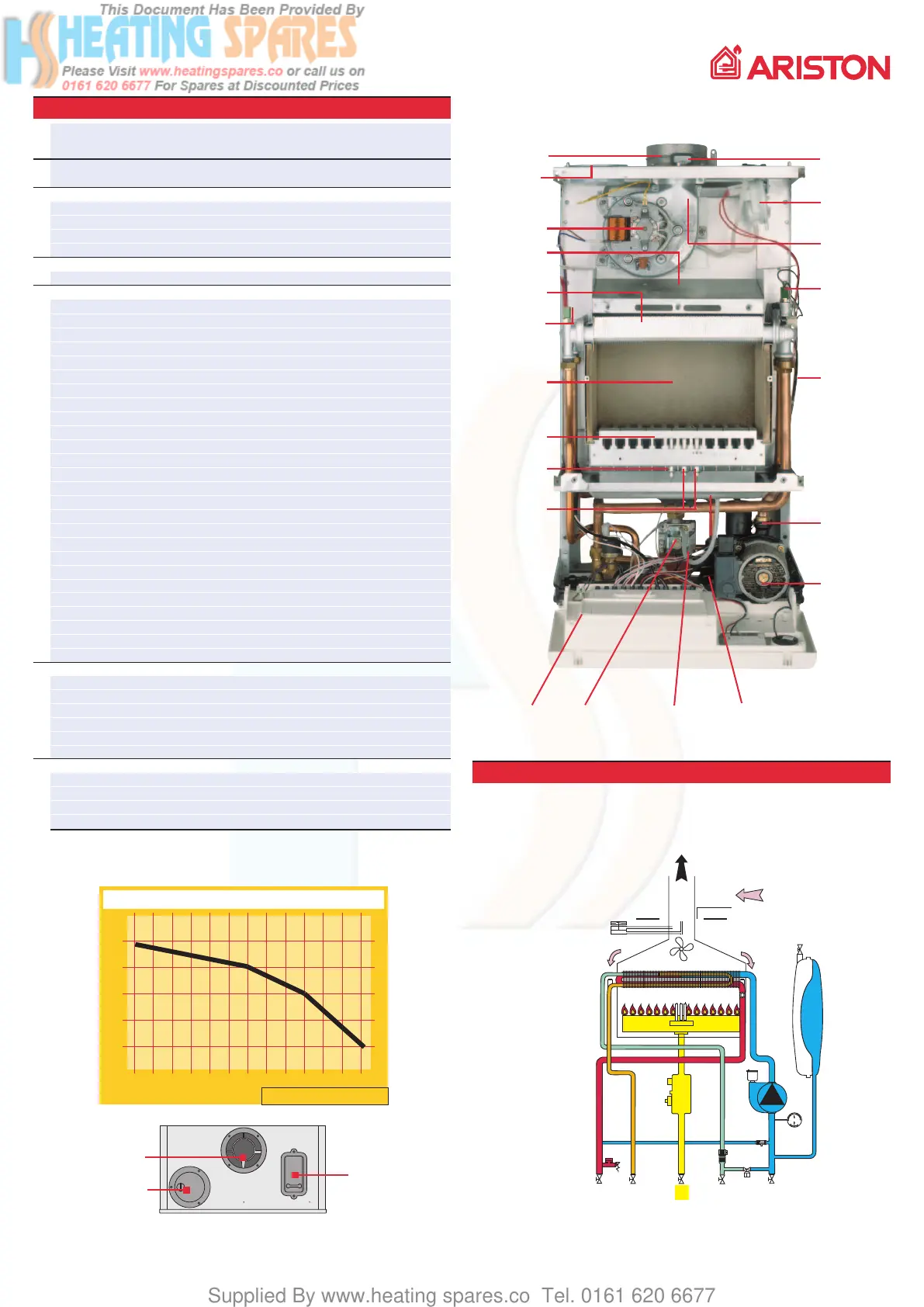
Flue
connector
Air
intake
Fan
Combustion
chamber
hood
“Twin-pass”
heat exchanger
Domestic hot water
temperature
probe
Combustion
chamber
Burner
Detection
electrode
Ignition
electrodes
Gas valve
Control
panel
Spark
generator
Water entry
filter
Combustion
analysis points
Air pressure
switch
Venturi
Expansion
vessel
3 bar safety valve
Circulation pump
with automatic air
release valve
Graph of boiler residual head
flow rate l/h
100 200 300 400 500 600 700 800 900 1000 1100 1200 1300
100
200
300
400
500
separation of the intake
simplified coaxial
system coupling
air pressure switch
can be accessed
directly from the
exterior
Central heating
temperature
probe
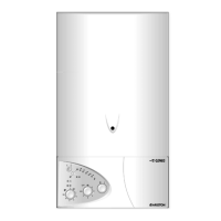
MICROCOMBI
23 MFFI
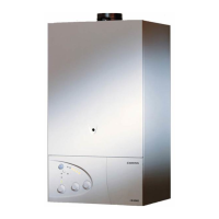
MICROCOMBI
27 MFFI
MICROCOMBI 27 MFFI
 Loading...