7
- The blue wire should be connected to the terminal marked “N”;
- The brown wire should be connected to the terminal marked “L”.
Note: The diagrams for the electrical system are indicated in section 2.12.
Warning, this appliance must be earthed.
External wiring must be correctly earthed, polarised and in accordance with relevant
regulations / rules. In GB this is the current I.E.E. WIRING REGULATIONS. In IE
reference should be made to the current edition of the ETCI rules. This boiler is
supplied f
or connection to a 220 - 240 V~ 50 Hz supply.
The suppl
y must be fused at 3 A.
The method of connection to the electricity supply must facilitate complete electrical
isolation of the appliance
, by the use of a fused double pole isolator having a contact
separation of at least 3 mm in all poles or alternatively, by
means of a 3 A fused
three pin plug and uns
witched shuttered socket outlet both complying with BS 1363.
The point of connection to the Electricity supply must be readily accessible and
adjacent to the appliance unless the appliance is installed in a bathroom when this
must be sited outside the bathroom (see section 2.3).
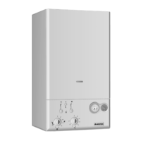
2.10 WATER CONNECTIONS
FIG. 2.4
VIEW
OF THE
BOILER CONNECTIONS
FIG. 2.3
A
F
LEGEND:
A = Central Heating Flow
C = Gas Inlet
E = Centr
al Heating Return
F = Saf
ety
V
alv
e
G = Pump tr
anspor
tation scre
w
(remo
v
e before igniting the boiler)
H = A
utomatic By-Pass Pipe
H
C
E
G
SC004A
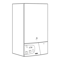
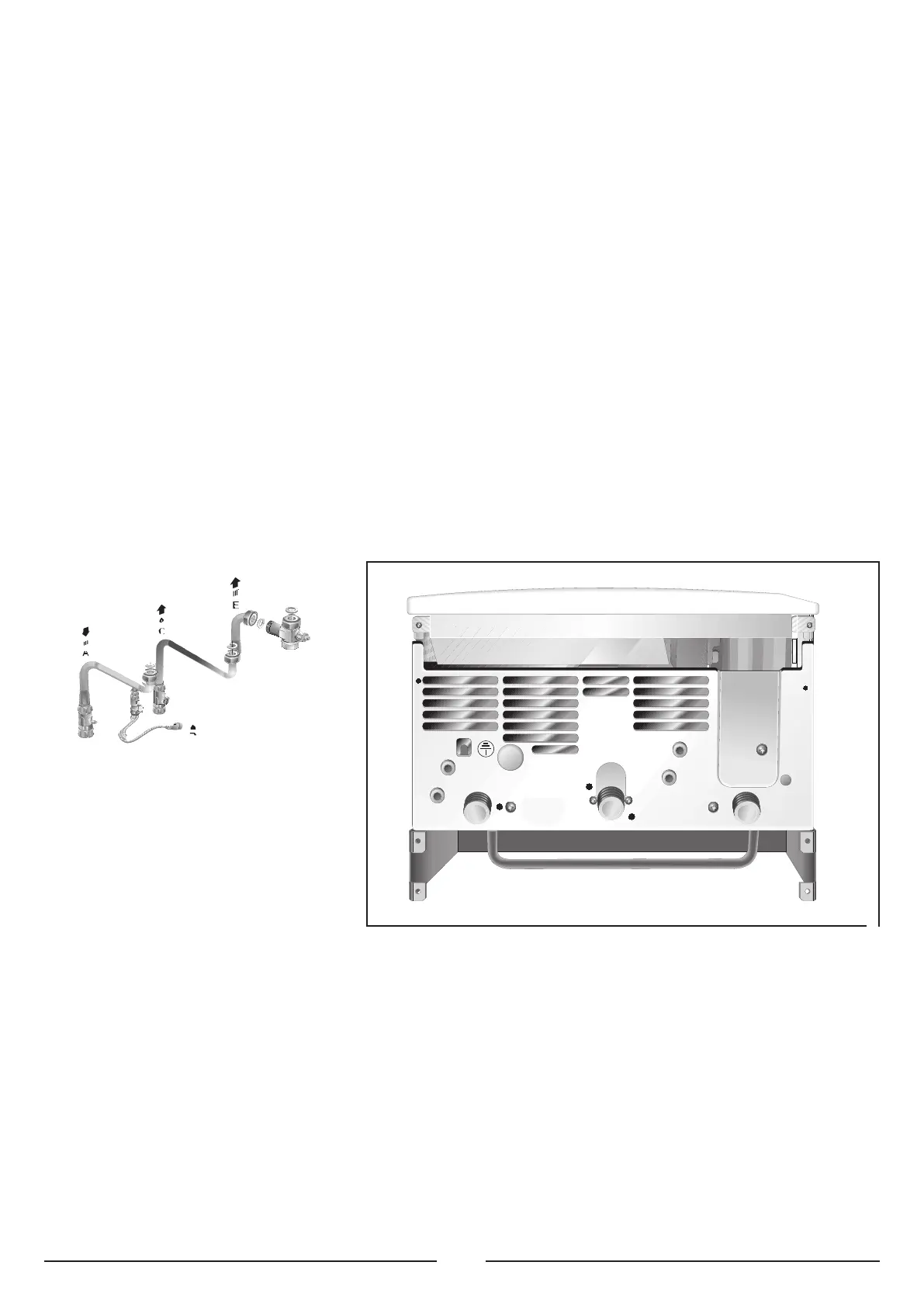
2.9 GAS CONNECTION
The local gas region contractor connects the gas meter to the service pipe. The gas
installation should be in accordance with the relevant standards. In GB this is
BS6891 and in IE this is the current edition of I.S.813. The connection the the
appliance is a 22mm copper tail located at the rear of the gas service cock (
FIG. 2.3).
If the gas supply for the boiler serves other appliances ensure that an adequate
supply is a
vailable both to the boiler and the other appliances when they are in use
at the same time. Pipe work must be of an adequate size. Pipes of a smaller size
than the boiler inlet connection should not be used.
CENTRAL HEATING
Detailed recommendations are given in BS 6798:1987 and BS 5449-1:1990,
the following notes are given for general guidance.
PIPE WORK
Copper tubing to BS EN 1057:1996 is recommended for water pipes.
Jointing should be either with capillary soldered or compression fittings.
Where possib
le pipes should ha
ve a gradient to ensure air is carried
naturally to air release points and water flows naturally to drain taps.
The appliance has a built-in automatic air release valve, however it
should be ensured as far as possible that the appliance heat exchanger
is not a natural collecting point for air.
Except where providing useful heat, pipes should be insulated to prevent
heat loss and avoid freezing.
Particular attention should be paid to pipes passing through ventilated
spaces in roofs and under floors.

 Loading...