62 / GB
ANODE
SE TNK
BUS
TA 1 TA 2
B T
IN
AUX 1+24V
N LN L
PM AUX
AUX 1
OUT
V 1
V 2
ST 1
HV
IN 3
HV
IN 1
HV
IN 2
MOD. BUS
GND A+ B-
L N L N
NN
L
321
LL
NN
L
321
LL
70 - 90 110 S (1ph)
40 50 S
70 - 90 110 S -T (3ph)
L
LL
230V
N
L N
A
B
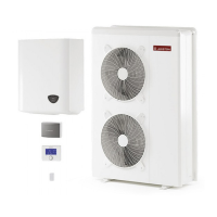
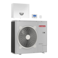
Internal Unit electrical connection
efore any operation on the system, turn o the main power. Observe the
phase and neutral connections.
To access the control panel of the internal unit, proceed as follows: Remove
the three screws (A) indicated in gure and remove the cover of the electrical
panel (B).
When opening the internal unit, you will fi nd the following connec-
tions:
MOD BUS
- Communication with the external unit. Observe the polarities.
ANODE - Tank Protech anode connection.
Observe the electrical polarities.
TA1 - Ambient contact thermostat connection, zone 1.
TA2 - Ambient contact thermostat connection, zone 2.
SE - Outdoor temperature sensor connection.
TNK - Tank sensor connection.
BUS - Remocon Plus connection.
IN-AUX - Humidistat/auxiliary input connection.
HV IN 3 - 230V Input. Select the operation mode by the parameter
17.1.2.
PV Integration: through this input is possible to use the DHW
tank as energy storage in case of a surplus of energy pro-
duction by a PV system. Connect the output contact from an
energy meter to the PV input, the output contact is closed
when the energy production is higher than a threshold set-
table on the energy meter.
HV IN 1 - 230V Input. Select the operation mode by the parameter
17.1.0.
•EDF (Night tariff): applying a 230V signal to the input
the tank charge is enabled according to the DHW modes HC-
HP or HC-HP 40°C selectable by the parameter 17.5.2
•SG Ready 1: input signal nr 1 for the SG Ready standard (see
paragraph SMART GRID READY STANDARD).
HV IN 2 - 230V Input. Select the operation mode by the parameter
17.1.1.
•DLSG (load shedding): this input signal, if supplied by the
electrical grid provider, disable the heating resistors.
•SG Ready 2: input signal nr 2 for the SG Ready standard (see
paragraph SMART GRID READY STANDARD).
OUT-AUX
1- Auxiliary output, free potential contact
(see parameter 17.1.4)
ST1 - Safety thermostat connection (230 V)
for under-fl oor system (shunt connection).
PM AUX- Auxiliary pump connection.
V1 - Diverter valve connection for domestic water circuit
V 2 - Diverter valve connection for cooling circuit
L 1 - Three-phase power phase 1 connection (230 V)
for internal unit
L 2 - Three-phase power phase 2 connection (230 V)
for internal unit
L 3 - Three-phase power phase 3 connection (230 V)
for internal unit
N - Connection of the neutral point (230 V) of the internal unit .
- Earth connection of the internal unit .
The size and length of the cables must be sized according to the
power indicated on the data plate of the internal unit.
Ensure that the power cables are properly tightened in order to avoid
overheating.
WARNING
After carrying out the connections between the indoor and ou-
tdoor units, put back both panels of the respective units.
Low voltage terminal block of
internal unit
High voltage terminal block of
internal unit
Power supply terminal block of internal unit
 Loading...