Do you have a question about the Ariston NIMBUS PLUS 50 S EXT and is the answer not in the manual?
Explains the meaning of warning symbols used in the manual.
Information on proper disposal of the product at the end of its life.
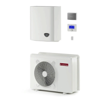
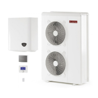
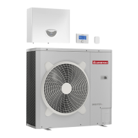
Lists the components that make up the NIMBUS PLUS system.
Lists the available models for the external unit and their dimensions.
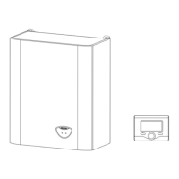
Provides weight and dimensional data for the internal units.
Labeled diagram illustrating the components of the internal unit.
Charts showing restrictions for cooling operation based on temperatures.
Charts showing restrictions for heating operation based on temperatures.
Graphs and tables detailing available pressure for different unit sizes.
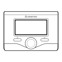
Technical specifications for the system interface.
Instructions for positioning and installing the outdoor sensor.
Key considerations and warnings before installing the appliance.
Guidance on choosing the optimal location for the external unit.
Specifies the minimum clearance requirements for installation.
Initial steps and considerations for positioning the indoor unit.
Required clearances for maintenance and proper operation of the indoor unit.
Information on the expansion vessel for heating systems.
Guidelines for handling, storing, and preparing refrigerant pipes.
Step-by-step process for purging air from connecting pipes.
Detailed procedure for charging the refrigerant gas into the system.
Procedure to recover refrigerant gas for maintenance operations.
Checks and procedures for water circuit connections on the indoor unit.
Specific note regarding installation with under-floor heating systems.
Details on the electrical circuit and safety checks for installation.
Tables detailing electrical connection specifications for units.
Guidance on choosing the optimal location for the system interface.
Instructions for mounting the system interface on the wall.
Details on connecting the system interface to the internal unit.
Explains the meaning of various symbols displayed on the interface.
Identifies and explains the function of buttons and LED lights.
Steps to enter the technical parameters and settings menu.
Navigating and configuring user-specific parameters.
Configuration of energy manager parameters.
Setting the hydraulic configuration of the installation.
Settings related to the central heating system operation.
Defining modes for floor drying cycles.
Activating refrigerant gas recovery for maintenance.
Parameters for controlling Zone 1's temperature and settings.
Configuration of thermoregulation types and temperature adjustments.
Adjusting the slope and offset for thermoregulation curves.
Setting the cooling temperature setpoint for Zone 1.
Defining the cooling temperature range for Zone 1.
Selecting the thermoregulation type for cooling.
Diagnostic information for Zone 1 parameters.
Settings for Zone 1 module functions like pump modulation.
Settings for Zone 2, including temperature range and thermoregulation.
Diagnostic information for Zone 2 parameters.
Settings for Zone 2 module functions like pump modulation.
General configuration options for zone modules.
User-configurable parameters for the heat pump system.
Configuration of energy manager input and output signals.
Settings for central heating operation, including pump control.
Settings for cooling operation, including mode and anticycling.
Configuration of domestic hot water settings and comfort functions.
Manual activation of system components and circulator control.
Manual control functions for heat pump and cooling modes.
Access to test functions and utilities like air-purge.
Displays HP system sensor data (temperatures, flow).
Displays HP system status and error information.
Displays HP compressor and fan operational data.
Displays energy manager input/output status and values.
Lists essential annual checks for system safety and operation.
Explains the frost protection mechanism for external and internal units.
Advises the user on proper operation and periodic checks.
Details found on the internal unit's data plate.
Details found on the external unit's data plate.
| Type | Air-to-water heat pump |
|---|---|
| Heating Capacity | 5.0 kW |
| Cooling Capacity | 4.5 kW |
| Energy Efficiency Class (Heating) | A++ |
| Energy Efficiency Class (Cooling) | A+ |
| Refrigerant | R32 |
| Max. Water Temperature | 60°C |
| Heat Output | 5.0 kW |
| Power Supply | 230V |