2 / 24 P/N 1988072435 MA-466-5546-ML • REV E • ISS 23DEC20
4
EN: Installation Sheet
Description
CDC-2DWIF Dual Wiegand Interface provides two Wiegand
interfaces, as well as additional inputs. It is used to connect
additional readers, door contacts and door locks to the CDC4
door controller.
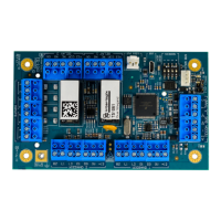
Figure 1: Module layout
(1) +12, −, D+, D−: Terminals to the CDC4 system data bus cable
(BUS1 or BUS2). Only use if 4-pin plug-in socket (item 14) is not
used.
(2) T, C: Terminals to the panel tamper switch in the enclosure. Must
be closed if not used. Note: Panel tamper switch must only be
connected to one board in the enclosure.
(3) TEST 1 and TEST 2 jumpers. For future use.
(4) Tx LED.
(5) Rx LED.
(6) Address DIP switch.
(7) Micro-B USB port. For future use.
(8) LOCK PWR 2-pin plug-in socket for lock power cable from CDC4
door controller.
(9) Relay connections for two doors.
(10) Input terminals.
(11) Earth terminal.
(12) Two sets of Wiegand reader connections.
(13) TERM link for the data bus.
(14) 4-pin plug-in socket for easy data bus cable connection to the
CDC4 door controller BUS 1.
(15) Heartbeat LED.
Terminals
Table 1: Terminals
System data bus (Figure 1, item
1)
2-way lock power cable connector
(item 8)
Door contact inputs (item 10)
BZ, L1, L2, D1,
D0, 0V, +12V
Wiegand 1 interface connection
(item 12). See also “Wiegand
reader connection” on page 3.
BZ, L1, L2, D1,
D0, 0V, +12V
Wiegand 2 interface connection
(item 12). See also “Wiegand
reader connection” on page 3.
The device is only allowed to be serviced by dedicated service
personal.
WARNING: Electrocution hazard. To avoid personal injury or
death from electrocution, remove all sources of power and
allow stored energy to discharge before installing or removing
equipment.
Mounting
CDC-2DWIF is mounted inside the CDC4 door controller
housing. The possible mounting positions are shown in
Figure 4 as items 3.
Use the supplied standoff mounts and screws to install the
module.
Note: All 4 mounting points must be used.
Figure 4: CDC4 housing layout
(1) CDC4 door controller PCB
(2) Module earth leads
(3) Possible locations for CDC-2DWIF Dual Wiegand Interface
(4) Earth tabs on the CDC4 power supply unit
(5) CDC4 power supply unit
Earthing
WARNING: Correct earthing procedures must be followed.
Each CDC-2DWIF interface must be earthed as shown in
Figure 4.
Connecting to CDC4 door controller
The dual Wiegand interface can be connected to a CDC4 door
controller via the 4-pin RS-485 terminals (Figure 1, item 1).
INPUTS
1 C 2 C 3 C 4 C 5 C 6 C 7 C 8 C
RELAY EXPANDER PWR
ON
1 2 3 4
USB
ETHERNET
1
2
3
4
ADDRESS
1 2
TEST
LINKS
LINK
ACT
10/100
Mbps
HEART
BEAT
LOCK
PWR 1
BUS 1
EXPANDER SLOT 1
TERM
TERM
TERM
BUS 2 BUS 1
+12 - D+ D- +12 - D+ D-
Tx Rx
Tx Rx
LOCK
PWR 2
BUS 1
AC BATT1 BATT2 AUX POWER OUT PANEL TAMP RELAY 1 RELAY 2 RELAY 3 RELAY 4
+ - + - +12 -+12 +12 -- S-S+ D+- D- T C +12 COM NC NO 0V +12COM NC NO 0V +12 COM NC NO 0V +12 COM NC NO 0V
RX
TX
LICENCE KEY
~~
CDC4
CDC-2DWIF
(2)
(3)
(2)
(3)
(2)
(3)
(2)
(3)
(1)
(4)
(5)