- 3 -
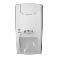
Figure : General characteristics of the VV600/602
Plus
1. Cover
2. Cover screw
3. Base plate
4. Mounting holes
5. Clamp
6. Area for mounting the VT705P test transmitter
7. Potentiometer for adjusting the detector’s sensitivity
8. Connection block
9. Anti-tamper micro-switch
10. Mounting plate VM600P
11. Fixing bolt
12. Expander bolt
13. Test transmitter VT705P
Using the mounting plate VM600P as a template
A. Holes for VV600/602 Plus
B. Holes for Securitas SSD70
C. Holes for Cerebus GM31/35/550/560
D. Hole for expansion plug or recess mounting box
E. Holes for Securitas 2000
F. Template and mounting holes for test transmitter VT705P
G. Holes for accessories.
Figure : Mounting on concrete
Always use a VM600P mounting plate. The expansion plug must
penetrate at least 50 mm into the concrete. Please follow the
steps shown in Figure 6 if you are installing the test transmitter
VT705P.
For the equipment to conform to CEI standard 79-2, the
VT705P test transmitter must be installed.
Figure : Mounting the detector on a metal
surface using the VM604P weld-on plate
First weld points 1, 2, 3, and 4. Then weld seams 5 and 6.
Figure : Two ways to test the seismic detectors
Test disabled (ex-factory setting)
Internal test of detector’s electronics = Position jumper
between 1 and 2 .
Function test of the detector and its physical contact with the
protected object = Position connector from test transmitter
VT705P between 2 and 3.
Connecting terminal 10 to 0 V activates both tests.
!
Detection range (in meters):
Figure : Control and function test
Using a voltmeter, check the background signal level in the
detector to prevent nuisance alarms. Set the sensitivity to Gmax
during the test.
VV600 Plus VV602 Plus Measure
0.7 V 0 V None
1.4 V 2 V Reduce range/remove source
Try to remove the source of ambient noise instead of
reducing the range.
Functional testing with hand tester VT610P " and mechanical
tool
#:
VV600 Plus VV602 Plus
Alarm in 30 sec. Alarm in 45 sec.
Alarm after 5 blows NA
!
!
Concrete 4 14 14
Steel 1/G
max
81414
Brick 3 8 8
Concrete 3 9 9
Steel 2/G
ref
499
Brick 1 6 6
Concrete 2 6 6
Steel 3/G
min
266
Brick - 4 4
Concrete 1 5 5
Steel 4 1 5 5
Brick - 3 3
Concrete - 4 4
Steel 5 - 4 4
Brick - 2 2
Technical specifications:
Input power: 9-15 VDC
2 V max. ripple pp
Current
consumption: Nom. 8.6 mA
Alarm output: Form A solid state relay, max. series
resistance 35 Ohm
Alarm indication: LED-ind. output 3
Sensitivity: 5 steps of 6 dB each
Range: See Table “Detection range”
Sabotage protection: Temp. 84°C,
drill shield,
opening/pry-off contact,
Low voltage alarm: 7.5 V
Temperature limits: -20°C to +55°C
Dimensions: 101 x 81 x 28 mm
Colour: Grey, RAL 7035
Weight: 380 g
5
2
7
6
Figure : Mounting the detector directly on a
metal surface without using a mounting
plate
4
Sensitivity
setting
Material Thermal
lance
Diamond
disk
Drilling
3
Figure : Wiring diagram
1/2. 12 VDC
3. LED indication
4. Integrator level
5/6. Alarm output
7. Spare
8/9. Tamper
10. Test control
11. Spare
1
1
2
3
GB
 Loading...