EasyManua.ls Logo

Aritech 700 series User Manual

Aritech 700 series
4 pages
To Next Page IconTo Next Page
Page #1 background imageLoading...
Page #1 background image
(part number) © 2000-2002 Interlogix B.V.
All rights reserved
A
A: 2-wire wiring
B: 4-wire wiring
À Fire alarm initiating circuit
Compatible listed control unit
Continuity switch
First detector
Remote indicator device
Last detector
End-of-line device
13
2
13
2
64
5
13
2
64
5
1
+
-
4
5
7
64
5
3
2
6
7xxI 7xxI 7xxI
B
A: 2-adrige Verdrahtung
B: 4-adrige Verdrahtung
Auslöseschaltkreis für
Feueralarm (C)
Kompatible, zugelassene
Steuereinheit
Überbrückungsschalter
Erster Detektor
Fernanzeigegerät
Letzter Detektor
Endgerät
A: 2-leder kabling
B: 4-leder kabling
Brannalarm detektorkurs
Kompatible brannalarmsentraler
Forbindelsesbryter
Første detektor
Ekstern indikatorenhet
Siste detektor
Endemotstand
A: 2-trådsinkoppling
B: 4-trådsinkoppling
Detektorkrets
Kompatibel centralapparat
Brytande sockelkontakt
Första detektorn
Fjärrindikeringsenhet
Sista detektor
Ändmotstånd
A: 2-trådet ledningsføring
B: 4-trådet ledningsføring
Brandalarm initieringskredsløb
Kompatibel styreenhed
Vidrekoblingskontakt
Første detektor
Fjernindikator
Sidste detektor
Endemodstand
A: 2-juhtmeline ühendus
B: 4-juhtmeline ühendus
Tulekahjualarmi käivitusahel
Ühilduv kontroller
Sildav lüliti
Esimene andur
Kaugindikaator
Viimane andur
Liini lõputakisti
A: 2-laidis jungimas
B: 4-laidis jungimas
Gaisro signalo generavimo grandinė
Suderintas priešgaisrinis pultas
Grandinės vientisumo trumpiklis
Pirmas jutiklis
Nutolinis indikatorius
Paskutinis jutiklis
Kontrolinė apkrova
A: 2 vadu elektroinstalācija
B: 4 vadu elektroinstalācija
Ugunsgrēka signāla iniciācijas ķēde
Saderīga ugunsdrošības vadības pults
Pārejas slēdzis
Pirmais detektors
Ārējais indikators
Pēdējais detektors
Līnijas rezistors
GB
N
EST
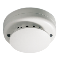
700 Series Commercial Self-Diagnostic
Smoke Detectors
Installation and Service Manual
LVLT
S DK
D
WWW.UKPANELS.COM

Other manuals for Aritech 700 series

Question and Answer IconNeed help?

Do you have a question about the Aritech 700 series and is the answer not in the manual?

Aritech 700 series Specifications

General IconGeneral
Detection Angle90°
Operating Temperature-10°C to +55°C
TechnologyPIR
CoverageArea
Mounting Height Recommended2.4 meters
Alarm OutputNormally Closed (NC)
Tamper OutputNormally Closed (NC)
Humidity Range95% RH non-condensing
Detection PrinciplePassive Infrared

Summary

INSTALLATION

Fire Sensor Placement and Spacing

Guidance on optimal placement and spacing of smoke detectors to prevent false alarms and ensure coverage.

Where NOT TO Place Sensors

Identifies locations to avoid for sensor placement to prevent nuisance alarms from steam, fumes, or high temperatures.

Installing the Detector Head

Instructions on how to correctly insert and lock the detector head into its base for proper system connection.

Consider the Locking Mechanism BEFORE Installation

Details on the break-away locking tab for preventing unauthorized removal and how to use it.

TESTING THE SYSTEM

Procedure for applying power and checking for alarms after installation, including initial troubleshooting steps.

TESTING EACH DETECTOR

Annual Testing and Aerosol Use

Recommendations for annual testing of smoke detectors, including proper use of test aerosols to ensure alarm response.

Heat Detector Testing

Procedure for testing heat detectors using a hot air gun, specifying distance and expected alarm response time.

MAINTENANCE, CLEANING AND SENSITIVITY TESTING

Detector Trouble Indication

How the unit indicates trouble by flashing its LED every second if sensitivity drifts or diagnostic tests fail.

Photoelectric Detector Cleaning

Steps for cleaning the sensing chamber of photoelectric detectors and replacing the optical block for continued operation.

Sensitivity Level Test Mode

Explanation of the sensitivity level test mode, LED indicators for fault detection, and interpretation of sensitivity test results.

Related product manuals