MOUNTING INSTRUCTIONS
1. Choose the mounting position for the GS620N detectors on the structure
to be protected, having regard to the structures ability to transmit vibrations,
etc. Note that the universal sensor can be mounted on a horizontal plane
e.g. on a flat ceiling or under a door lintel.
2. Remove the detector cover and secure the base-plate to the structure
either vertically or horizontally as required.
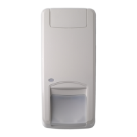
3. Orientate the sensor module so that the ARITECH-logo is upright and in the
readable position (fig. 1).
4. Route cabling into the unit and wire the unit as shown in fig. 2.
5. Ensure that the screws of the sensor module are secure (fig. 1 À).
6. When all sensors in the system are fully wired, disable (fig. 2 À) or enable
(fig. 3 À) the dual loop resistors with jumper J2.
7. Set the appropriate Control Voltage (CV) for the LATCH and LED-ENABLE
input of the device with jumper J1 (fig. 2 & 3 Á)
8. Apply power to the system. The alarm relay and the LED of each unit are
activated for a period of 4 seconds.
9. Program each unit for GROSS ATTACK and PULSE COUNT.
10. Replace the cover and secure it with the screw.
Fig.1. Sensor head
DUAL LOOP SELECTION
When the GS620N is used together with an Aritech control panel, the dual
loop option can be selected. In this configuration the alarm loop and the tamper
loop are combined into one loop using 4K7-resistors. The dual loop option can
be selected with jumper J2. If J2 is placed, the dual loop is selected.
See fig. 3 Â for contact configuration in dual loop mode.
Remove J2 in standard applications.
Fig. 2. Standard application (jumper J2 removed)
GS620N Stand-alone Inertia Shock Detector
Installation Manual
Fig. 3 Dual loop application (jumper J2 placed)
CONTROL VOLTAGE SELECTION (CV)
The detector can be remote controlled via the LATCH and LED-ENABLE in-
puts. The Control Voltage (CV) of these inputs can be selected with the
polarity jumper J1 (fig. 2 & 3 Á).
When jumper J1 is placed, the control voltage is set to 12 V. Removing jumper
J1 sets the control voltage to 0 V.
When the Control Voltage is applied to an input, this input is activated.
LED ENABLE/DISABLE
For test purposes the LED of the device can be enabled via the LED-ENABLE
input. Activating the input enables the LED.
The LATCH input must NOT be activated to ENABLE the LED indication for
testing!
GROSS ATTACK & PULSE COUNT PROGRAMMING
1. ENABLE the LED indication by activating the LED-ENABLE input. This
allows the LED to light up during programming.
2. To calibrate the unit for GROSS ATTACK, set both the switches 1 & 2 to
ON. In this position the PULSE COUNT circuit is disabled. In this setting
the relay can only be activated by a GROSS ATTACK.
3. The LED will light up for one second every time the sensor detects a
shock. An alarm event (relay trip) indication is given when the LED re-
mains lit for approximately 4 seconds.
4. When the GROSS ATTACK level required for activating the alarm has
been set, select the PULSE COUNT required for alarm activation with the
switches 1 & 2. See Table 1 for PULSE COUNT setting.
5. Using the GROSS ATTACK switches 3 & 4 for sensitivity adjustment,
apply high level shocks to the structure, using the LED as a guide to when
the alarm relay trips (LED on for 4 seconds). See Table 2 for the position
of switch 3 & 4 for each GROSS ATTACK level.
Note: PULSE COUNT signals are counted at 1-second intervals and
stored in a 30-seconds digital memory. These small signals de-
tect an intruder gently prising open a window or doorframe etc.
6. To test the PULSE COUNT setting, create small shocks on the structure
below the gross attack level. Each time a shock is detected and regis-
tered in memory, the LED will light up for 1 second. When the programmed
pulse count is reached, the alarm relay will trip and the LED remaining on
for 4 seconds indicates this. If the PULSE COUNT is not reached within
30 seconds or the alarm relay trips, the stored pulses are cancelled. After
- 1 -
F
D
I
E
S
GB
1
2
2
1234
1234
5678
5678
J2
J2
J1 J1
ON
ON
1234
1234
LED enable LED enable
Latch Latch
0V 0V12 V 12 V
11
Control
Panel
Latch
(arm/disarm)
0V
12 V
Alarm Loop
Tamper Loop
LED Enable
33W
33W
2
3
1234
5678
J2
J1
ON
1234
LED enable
Latch
12 V0V
1
Latch
(arm/disarm)
LED Enable
Dual Loop Zone
4K7
4K7
33W
Control
Panel
X
X
X Do not connect terminals4&6
0V
12 V
NL