cancellation a new detected pulse starts a new 30 seconds memory time.
Note: If only gross attack level activation is required, set both
switches 1 and 2 to ON.
7. De-activate the LED-ENABLE input after programming GROSS ATTACK
and PULSE COUNT. This ensures that the LED does not light. Therefore
window cleaners etc. cannot see the sensitivity level or the area of
cover.
Table 1.
PULSE COUNT PROGRAMMING
Switch 1 Switch 2 Pulse counts
off off 4
on off 6
off on 8 (*)
on on pulse count disabled
Table 2.
GROSS ATTACK PROGRAMMING
Switch 3 Switch 4 Gross level sensitivity
off off (max. sensitivity)
on off 2
off on 3
on on 4 (min. sensitivity) (*)
(*) = Factory setting.
ALARM MEMORY
The GS620N can latch alarm events into a memory. The memory function can
be enabled by the LATCH input.
When the system is armed, the LATCH-input of the detector should be acti-
vated (apply CV to input). The LATCH terminal is normally connected to the
LATCH or ARM/DISARM terminal of the control panel (fig. 2). Select the appro-
priate Control Voltage with jumper J2. Activation of the LATCH-input resets the
GS620N alarm memory (reset old alarms) and sets the detector to latch-
mode. No LED indication is possible in this mode. In latch-mode every detector
will latch an alarm into the alarm memory.
The LED-ENABLE input selects in which memory the alarm is stored. If the
LED-ENABLE input is NOT activated, the alarm is stored into the First to Alarm
memory (FTA), indicating this sensor came into alarm first. When the LED-
ENABLE input is activated, the alarm will be latched into the Subsequent to
Alarm memory (STA) indicating the sensor subsequently came into alarm.
To ENABLE the STA memory function the LED-ENABLE input of the detector
can be connected to a ALARM LATCH output of the control panel, which
activates the LATCH inputs of all detectors after a alarm (fig. 2).
When the LED-ENABLE input is not connected, the alarms will always be
stored into the First to Alarm memory.
When the system is disarmed, the LATCH-input should be de-activated.
Any device with an alarm stored into its memory will indicate this with its LED.
A slow flashing LED indicates a First to Alarm storage.
A steady ON LED indicates a Subsequent to Alarm storage.
Note: An activated LED-ENABLE input overrules the memory indica-
tion of the device and does NOT reset the alarm memory of the
device.
The next time the system is armed, the LATCH input is activated and the alarm
memory of the detector is reset. The LED is disabled.
TECHNICAL DATA
Supply voltage 8 to 15 V (12 V nom.)
Peak to peak ripple 2 V max. at 12 V
Current consumption
Normal operation 8.0 mA
Alarm (LED off) 2.5 mA
No alarm / LED on (memory) 14.5 mA
Alarm output 100 mA at 28 V
Alarm time min. 3 sec
Tamper output 100 mA at 28 V
Operating temperature -20 ° C to +50 ° C
Weight 45 g
Dimensions 93 x 30 x 24 mm
Housing meets IP30 IK02
Designed to conform to BS4737.
- 2 -
GS620A Détecteur Inertiel De
Chocs, A Analyse Intégrée
INSTRUCTIONS DE MONTAGE
1. Choisissez lemplacement où vous allez monter les détecteurs GS620A sur
la structure qui doit être protégée en tenant compte de la capacité de cette
structure à transmettre les vibrations, etc. Notez que le détecteur peut être
monté sur un plan horizontal comme, par exemple, sur un plafond plat ou
sous un linteau de porte.
2. Retirez le capot du détecteur et fixez lembase sur la structure, soit
verticalement, soit horizontalement, selon le cas.
3. Orientez le module de détection de façon à ce que le logo ARITECH soit lisible
normalement de gauche à droite (fig. 1).
4. Acheminez les câbles dans lunité et raccordez-les à lunité comme indiqué
à la fig.2.
5. Veillez à ce que les vis du module de détection (fig. 1 À) soient serrées
correctement.
6. Une fois que tous les détecteurs du système sont entièrement câblés,
désactivez (fig. 2 À) ou activez (fig. 3 À) la boucle à double résistances
à laide du cavalier J2.
7. Réglez la tension de commande CV (Control Voltage) pour lentrée LATCH
(MÉMORISATION) et LED-ENABLE (ACTIVATION DE LA LED) de lunité à
laide du cavalier J1 (fig. 2 et 3 Á).
8. Mettez le système sous tension. Le relais dalarme et la LED de chaque unité
sont activés pendant une période de 4 secondes.
9. Programmez le mode GROSS ATTACK (ATTAQUE FORTE) ET PULSE
COUNT (COMPTAGE DIMPULSIONS) POUR CHAQUE UNITÉ.
10. Remettez le capot en place et fixez-le à laide de la vis.
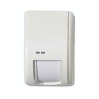
Fig. 1. Tête du détecteur
11. La fixation par vis devra être effectuée en ultilisant les 3 trous disposés sur
lembase dont 1 est placé sous le module de détection.
12. Pour que le matériel soit de type 3, la fixation devra seffectuer
IMPERATIVEMENT PAR COLLAGE ET PAR VISSAGE, sur support métallique
ou verre, avec une colle élastomère à basse de silicone, sure autres
supports, après encollage des deux parties, avec une colle à base de
néoprène. Le matériel sera de type 2 dans les autres cas.
SÉLECTION DE LA DOUBLE BOUCLE
Lorsque le GS620A est utilisé avec une centrale dalarme Aritech, loption de
double boucle peut être sélectionnée. Dans cette configuration, la boucle
dalarme et la boucle dautoprotection sont combinées en une seule boucle à
laide de résistances 4K7. Loption de double boucle peut être sélectionnée à
laide du cavalier J2. Si J2 est mis en place, la double boucle est sélectionnée.
Reportez-vous à la fig. 3 Â pour une configuration des contacts en mode double
boucle.
Retirez J2 dans les applications standards.
Fig. 2. Application standard (cavalier J2 retiré)
F
1
2
2
1234
1234
5678
5678
J2
J2
J1 J1
ON
ON
1234
1234
Activation
de laLED
Activation
de laLED
Mémoration Mémoration
0V 0V12 V 12 V
11
Central
d'Alarme
Mémoration
(armement/
désarmament
0V
12 V
Boucle
d'Alarme
Boucle
d'auto-
protection
Activation
de la LED
33W
33W
 Loading...