EasyManua.ls Logo

Aritech ATS 500A Series - User Manual

Aritech ATS 500A Series
18 pages
Print Icon
To Next Page IconTo Next Page
Loading...
© 2022 Carrier 1 / 18 P/N 466-5570 (EN) • REV E • ISS 22MAR22
Advisor Advanced ATSx500A Installation Sheet
EN
Figure 1: Small metal housing (-SM)
Figure 2: Medium metal housing (-MM)
RxTx
USB
MI
IP
CON12
CON13
T1
T2
S4 S5
+
+
S1
C
+
S2
C
T C
+
+
- -
1 C 2 3 C 4 5 C 6 7 C 8
~
~
+ -
AC
BATT
LC-OUTPUTS
HC-OUTPUTS
SIR TMP AUX POWER
INPUTS
CT
+
S3
C
CON16
NTC
COMMS
+12V 0VD+ D-
RxTx
USB
MI
IP
CON12
CON13
T1
T2
S4
S5
+
+
S1 C
+
S2 C
T C
+
+
- -
1 C 2 3 C 4 5 C 6 7 C 8
~
~
+ -
AC
BATT
LC-OUTPUTS
HC-OUTPUTS
SIR TMP AUX POWER
INPUTS
CT
+
S3 C
CON16
NTC
COMMS
+12V 0VD+ D-
315
40
385
55
(1)
(1)
(1)
(1)
(1)
(1)
15
109.4
102.5
60
(2)
60
15
24.1
51
35
85
Question and Answer IconNeed help?

Do you have a question about the Aritech ATS 500A Series and is the answer not in the manual?

Overview

Advisor Advanced ATSx500A Installation Sheet

This document provides general information for the installation of the Advisor Advanced ATSx500A, a series of control panels for intrusion detection systems. It covers various housing types, PCB layouts, wiring diagrams, and detailed technical specifications, as well as regulatory compliance information.

Function Description

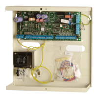
The Advisor Advanced ATSx500A is a series of intrusion control panels designed for security systems. These panels support various configurations, including different housing types (small metal, medium metal, large polycarbonate, large metal), and can be expanded with additional zones, outputs, keypads, and communication devices. The system is designed to detect and report alarms, manage access control, and provide system monitoring.

Key functionalities include:

  • Intrusion Detection: Supports single and dual loop zone wiring, allowing for detection of alarm, tamper, masking, and sensor fault states.
  • System Expansion: Connects to remote expanders (DGPs), I/O expanders, and keypads/readers to increase the number of zones, outputs, and user interfaces.
  • Communication: Utilizes system databus for device communication, Ethernet for IP connectivity (ATS-IP models), and can integrate with GSM/GPRS and PSTN modules for alarm reporting.
  • Access Control: Supports door controllers and intelligent doors, managing user access with various card ranges and protocols.
  • System Monitoring: Provides continuous monitoring of AC mains, battery status (low voltage, test fail), and power outputs (fuse/power output fail).
  • Wireless PIR Camera Functionality: Offers video verification features, fully compliant with standards.

Important Technical Specifications

Mains Power Specifications:

  • Mains Input Voltage: 230 VAC +10%, -15%, 50/60 Hz ±10%
  • Current Consumption at 230 VAC:
    • ATS1500A(-IP): 150 mA max.
    • ATS3500A(-IP), ATS4500A-IP: 300 mA max.
  • Transformer Output:
    • ATS1500A(-IP)-SM/LP: 20 VAC, 31 VA
    • ATSx500A(-IP)-MM/MM+/LM: 23 VAC, 58 VA
    • ATS3500A(-IP)-LP: 22 VAC, 53 VA
  • Mains Fuse: T-160 mA (ATS1500A(-IP)-SM/LP) or T-315 mA (ATS1500A(-IP)-MM, ATS3500A(-IP), ATS4500A-IP), 230 VAC, slow.

Power Supply Specifications:

  • Power Supply Type: Type A per EN 50131-6, Type I per VdS 2115
  • Power Supply Voltage: 13.8 VDC ±0.2 V
  • Power Supply Current:
    • ATS1500A(-IP): 1.10 A max. at 13.8 VDC ±0.2 V
    • ATS3500A(-IP): 2.10 A max. at 13.8 VDC ±0.2 V
    • ATS4500A-IP: 2.65 A max. at 13.8 VDC ±0.2 V
  • Main Board Consumption (Alarm / Idle):
    • ATSx500A: 100 mA at 13.8 VDC ±0.2 V
    • ATSx500A-IP: 150 mA at 13.8 VDC ±0.2 V
  • Maximum System Current Available:
    • ATS1500A: 1000 mA at 13.8 VDC ±0.2 V
    • ATS1500A-IP: 950 mA at 13.8 VDC ±0.2 V
    • ATS3500A: 2000 mA at 13.8 VDC ±0.2 V
    • ATS3500A-IP: 1950 mA at 13.8 VDC ±0.2 V
    • ATS4500A-IP: 2500 mA at 13.8 VDC ±0.2 V
  • Auxiliary Power Output (AUX. POWER): 13.8 VDC ±0.2 V, 1 A max.
  • Battery Power Output (BAT): 13.8 VDC ±0.2 V, 2.5 A max.
  • Battery Type: Lead acid rechargeable (7.2 Ah, 12 Ah, 18 Ah, 26 Ah, 36 Ah, 12 V nom.)
  • Battery Low Condition: From 9.5 to 10.5 VDC
  • Minimum Voltage (Battery Recharging): 9.45 VDC

General Features:

  • Code Combinations: From 10,000 to 10 billion (4-10 digits)
  • End-of-Line Resistor: 1 kΩ, 1.5 kΩ, 2 kΩ, 2.2 kΩ, 3.3 kΩ, 3.74 kΩ, 4.7 kΩ (default), 5.6 kΩ, 6.8 kΩ, 8.2 kΩ, 10 kΩ
  • Onboard Zones: 8 (expandable to 16 with 1X ATS608)
  • Maximum Zone Number: 32 (ATS1500A), 128 (ATS3500A), 512 (ATS4500A)
  • Onboard Outputs: 5 (expandable to 9 with 1X ATS624, or to 21 with 1X ATS626)
  • Maximum Output Number: 128
  • Areas: 4 (ATS1500A), 8 (ATS3500A), 64 (ATS4500A)
  • Maximum Keypad / RAS Number: 8 (ATS1500A), 16 (ATS3500A), 32 (ATS4500A)
  • Maximum Expander / DGP Number: 7 (ATS1500A), 15 (ATS3500A), 30 (ATS4500A)
  • Maximum User Number: 2000 (1000 full data, 1000 card-only users)
  • Event Log Capacity: 24500 events (10000 mandatory, 1500 non-mandatory, 10000 access, 1000 installer, 1000 dialler, 1000 extended)
  • Data Retention: 20 years
  • Access Control Features: Supports 7 (ATS1500A) or 12 (ATS3500A/ATS4500A) door controllers.
  • Ethernet Connection (IP only): IEEE 802.3u, 10BASE-T or 100BASE-TX, Half-duplex and full-duplex, FTP Cat 5e cable or better.
  • Operating Temperature: 0 to +40°C (Tested: -10 to +55°C according to EN 50131)
  • Humidity: 95% non-condensing
  • IP Protection Grade: IP31
  • Safety Class: Class I
  • Overvoltage Category: Category II

Usage Features

Housing Options: The ATSx500A series offers various housing options to suit different installation needs:

  • Small Metal Housing (-SM): Compact design for basic installations.
  • Medium Metal Housing (-MM and -MM+): Provides more space for components and larger batteries.
  • Large Polycarbonate Housing (-LP): Lightweight and durable, suitable for various environments.
  • Large Metal Housing (-LM): Robust and secure, ideal for demanding installations.

Pry-off Tamper Mount: All housings include a pry-off tamper mechanism to detect unauthorized opening or removal from the wall. Specific instructions are provided for mounting the tamper switch for different housing types.

System Databus Wiring: The system uses a shielded data cable with two twisted pairs (WCAT 52 recommended) to connect remote expanders and keypads. It supports both single and dual loop configurations, with termination jumpers or resistors required at the ends of the databus runs. For longer distances or separate power supplies, specific wiring guidelines are provided to ensure reliable communication and power delivery.

Zone Connection: Zones can be configured as standard EOL (End-Of-Line) freely programmable zones. Dual loop wiring allows for detection of multiple detector states (alarm, tamper, masking, sensor fault). The system supports various EOL resistor values and anti-masking options.

Battery Installation and Replacement: The system uses sealed, rechargeable lead-acid batteries. Detailed steps are provided for installing and replacing batteries, including safety warnings regarding incorrect battery types and handling. The system monitors battery status (low voltage, test fail) and performs daily tests to ensure proper operation.

Regulatory Compliance: The ATSx500A series is designed to comply with various international standards, including EN 50131 (Grade 2 and 3), EN 50136, INCERT, SES, and SBSC policies. Specific settings and configurations are required to meet these compliance levels, covering aspects like polling intervals, user group options, alarm reporting delays, and anti-masking.

Maintenance Features

Servicing: Maintenance and servicing of the intrusion control panel should only be performed by dedicated service personnel. The housing screw is designed to protect the product from unintended use.

Opening the Housing: To open the housing, the housing screw must be removed, and the cover opened. After maintenance, the cover must be replaced and secured with the screw. For plastic housings, the screw must be mounted before first-time use.

Mains Power Connection: Electrical installation must be carried out by a skilled person, adhering to relevant electrical installation regulations (e.g., BS 7671) and equipment manufacturer recommendations. Solid insulation of mains cables is required, and strain reliefs (cable ties, PG16 cable glands) should be used to minimize wire damage. The building protective earthing wire must always be connected reliably.

Battery Management: The system monitors battery voltage and disconnects the battery if it falls below a specified value to prevent deep discharge, as required by EN 50131 Grade 3 and VdS-C regulations. A specific fail message is generated if any output fails.

System Shielding: Shielding of all shielded cables should be connected at one side to one common earthing point in a building. This helps protect the system against variations in earth potential and electrical interference.

Cable Management: Avoid loops of wire inside the control panel cabinet. Cables should be routed neatly and secured with cable ties to prevent interference with the printed circuit board and improve overall neatness.

Tamper Protection: All joints in interconnection wiring should be mechanically and electrically secure. Conduit access points and junction boxes outside the supervised area must incorporate tamper detection, requiring a tool for removal of access covers.

Environmental Considerations: The units should be used in a clean environment and not in humid air. Minimum clearance of 50 mm between equipment enclosures is recommended.

Firmware Upgrades: The document mentions device firmware upgrade mode (DFU) via T2 terminal, indicating support for firmware updates to ensure the system remains current with the latest features and compliance requirements.

Aritech ATS 500A Series Specifications

General IconGeneral
BrandAritech
ModelATS 500A Series
CategorySecurity Sensors
LanguageEnglish

Related product manuals