Wiring
Your Floodlight must be wired to its own switch. For
installation/maintenance purposes the electrical supply must be
isolated at the switchboard by removing the fuse or switching the
circuit breaker OFF. Simply isolating the electrical supply at the
wall switch is not sufficient isolation to prevent an electrical shock.
The terminal block wired to the rear of the security light must be
wired to the switched active and neutral of the lighting circuit to
which it is being connected. Connect in accordance with the
wire colours, red to active, black to neutral. An earth/ground
connection is not necessary on this product.
If an earth wire is provided in the supply cable, ensure that it
is taped or tied in such a fashion that it will not work loose and
contact any connection inside the junction box or rear of the
Floodlight. Now press the terminal block onto plastic pins in
junction box, then fit the Floodlight mounting base onto the
junction box using screws provided.
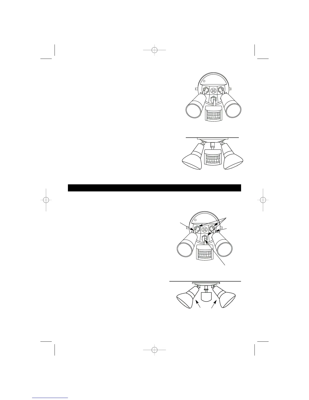
Ensure that the mounting base is in the correct direction so
that the sensor head controls will face downwards (See Fig. 5
and 6), and that the rubber seal on the rear of the mounting
plate is correctly positioned.
Setting Up
Do not overtighten or use excessive force when adjusting sensor head or lampholders.
Loosen lock nuts or elbow/joint scews to make
adjustment.
A. Adjust the direction of the sensor arm and
lampholders to suit the desired detection area.
Loosen lock nuts and elbow screws on lampholder
before making any adjustments. Do not use
excessive force when making adjustments to
lampholders (See Fig. 7).
B. Angle sensor slightly downward towards the
detection area. The sensor joint should be rotated to
adjust the sensor to face the required detection area.
If necessary, loosen sensor arm joint clamp screw.
C. Angle lampholders from mounting surface and direct
them approximately downwards away fromsensor
head.
D. Fit PAR38 globes and weatherproofing rubber
seals- do not overtighten.
E. Ensure that globes are positioned 40mm or more
from the sensor head or mounting surface as
shown in (Fig. 8). The globes become very hot and
must not be touching or too close to sensor head.
F. After fitting globes, tighten elbow screws and lock
nuts- do not overtighten.
Fig. 7
Lock nuts
Elbow
screw
Joint &
clamp
screw
40mm
Elbow
screw
Fig. 5
Fig. 6
Fig. 8
Wall mount
Eave mount
3
 Loading...