507746-01 Issue 1821 Page 1 of 39
NOTE: Special procedures are required for cleaning the all-aluminum coil in this unit. See Page 37 in this instruction
for information.
IMPORTANT INFORMATION FOR INSTALLER
A
B
C
HORIZONTA L DRAIN PAN (SEE
UPFLOW APPLICATIONS ON PAGE
6 AND DOWNFLOW APPLICATIONS
ON PAGE 8 )
BLOWER HOUSING SUPPORT PAD
REFRIGERANT LINE PLUGS (SEE
BRAZING CONNECTION ON PAGE 10)
CHECK FOR AND REMOVE THE FOLLOWING ITEMS BEFORE OPERATING UNIT.
FOR PROPER OPERATION THE ELECTRIC HEAT (IF APPLICABLE) MUST BE
CONFIGURED (SET-UP) THROUGH THE AIR HANDLER CONTROL (AHC)
ELECTRIC HEAT SECTIONS MUST BE
CONFIGURED. IF INSTALLED, SEE
PROCEDURE IN FIGURE 22 ON PAGE 31.
H
H
CONFIGURE ELECTRIC HEAT
ECB27
IMPORTANT: WHEN ELECTRIC HEAT IS INSTALLED, THE
AIR HANDLER CONTROL MUST BE MANUALLY
CONFIGURED. SEE JUMPERS AND LINKS GUIDE ON
PAGE 19.
Save these instructions for future reference
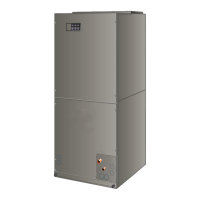
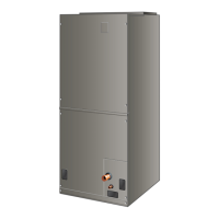
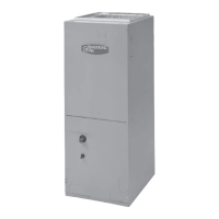
INSTALLATION INSTRUCTIONS
BCE7S Series Air Handler
(P) 507746-01
*P507746-01*
Manufactured By
Allied Air Enterprises LLC
A Lennox International, Inc. Company
215 Metropolitan Drive
West Columbia, SC 29170
This manual must be left with the homeowner for future reference.
This is a safety alert symbol and should never be ignored. When you see this symbol on labels or in
manuals, be alert to the potential for personal injury or death.
Table of Contents
Unit Dimensions ..........................................................2
Model Number Identication ........................................4
General Information ....................................................5
Shipping and Packing List ..........................................5
Installation Clearances ...............................................5
Requirements .............................................................5
Installation ...................................................................6
Brazing Connections ................................................10
Condensate Drain .....................................................12
Inspecting and Replacing Filters ..............................13
Sealing the Unit ........................................................13
Field Control Wiring ..................................................13
Air Handler Control Button, Display and Jumpers ....20
Unit Operating Sequences .......................................27
Operation ...................................................................35
Repairing or Replacing Cabinet Insulation ................36
Homeowner Maintenance..........................................36
Professional Maintenance .........................................37
Checkout Procedures ................................................37