Page 4 ?*,)(.82<&80;)@+.'(&*<'A)3;.0'.)80;;)BCDDDCD!!C$EFE5 Item 64355
GH?:IJ KLGIHMMHIKNL OHPIG)MKGI
K<'(0;;0(&*<)K<'(,+8(&*<'
)P.0=)(2.):LIKP:)KTONPIHLI)GH?:IJ)KL?NPTHIKNL)'.8(&*<)0()(2.)/.7&<<&<7)*6)(2&')
90<+0;)&<8;+=&<7)0;;)(.\()+<=.,)'+/2.0=&<7')(2.,.&<)/.6*,.)'.()+3)*,)+'.)*6)(2&')3,*=+8(5
L*(.1 The following tools (not included) are required for mounting and installation: Stud Finder,
Phillipsscrewdriver,5/32″drillbit(fordrillingintowoodstud),3/8″carbidetipmasonrydrill
bit(fordrillingintoconcretewall),minimum6″level,andwrenchorsocketset.
H((082&<7)(*)R**=)G(+='
QH[IKNLY Do not mount to steel wall studs.
1. Verifywoodstudsareatleast16″apart.
Use a Stud Finder (not included) to find two
adjacentstuds16″apart.Useamarker
to indicate locations of the studs.
RHPLKLSY Verify that mounting surface has no
hidden utility lines before drilling or driving screws.
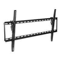
2. Set Wall Bracket (1) against the wall at the desired
height. Place a level over the upper or lower
cross bar and adjust Bracket until level. Use a
marker to indicate locations of mounting holes.
3. Drillfour5/32″holesatleast2-1/2″deep
into the studs at the marked locations.
RHPLKLSY Do not mount Wall Bracket to
drywall or plaster. Ensure that mounting
holes are located in wood studs.
4. Use four Lag Bolts (14) and Lag Bolt Washers (15)
to mount Wall Bracket to wall studs. Center
Bracket across mounting locations with mounting
holes flush against the wall. Refer to Figure A.
M07)
U*;()
]B"^
M07)U*;()
R0'2.,)]B$^
R0;;)U,08_.()]B^
?&7+,.)H)
H((082&<7)(*)Q*<8,.(.)R0;;
QH[IKNLY Do not mount to brick or cinder block wall.
Minimum 8 inch thick solid concrete is required.
1. Set Wall Bracket against the wall at the desired
height. Place a level over the upper or lower cross
bar and adjust Bracket until level. Use a marker
to indicate locations of mounting holes, two in
the top row of slots and two in the bottom. Allow
atleast6″ofspacebetweenanytwoholes.
2. Usea3/8″carbidetipmasonrydrillbitanddrillfour
holesatleast2-1/2″deepatthemarkedlocations.
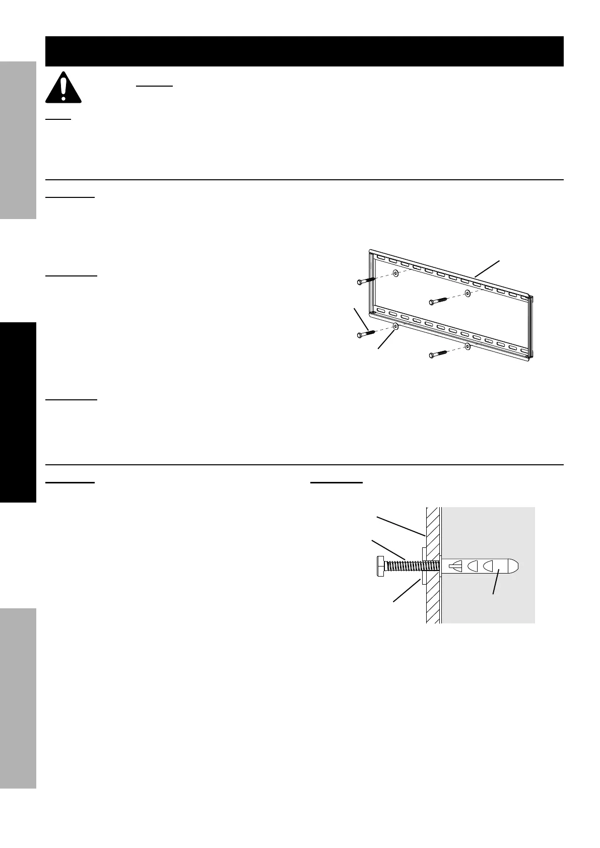
3. Insert the Concrete Wall Anchors (16) into the holes,
making sure they are flush with the wall surface.
RHPLKLSY))Concrete)Wall Anchors must be
set firmly into concrete. See Figure B.
Concrete
Q*<8,.(.)R0;;)
H<82*,)]B!^
M07)U*;()
R0'2.,))
]B$^
R0;;)U,08_.()]B^
M07)
U*;()
]B"^
?&7+,.)U
 Loading...